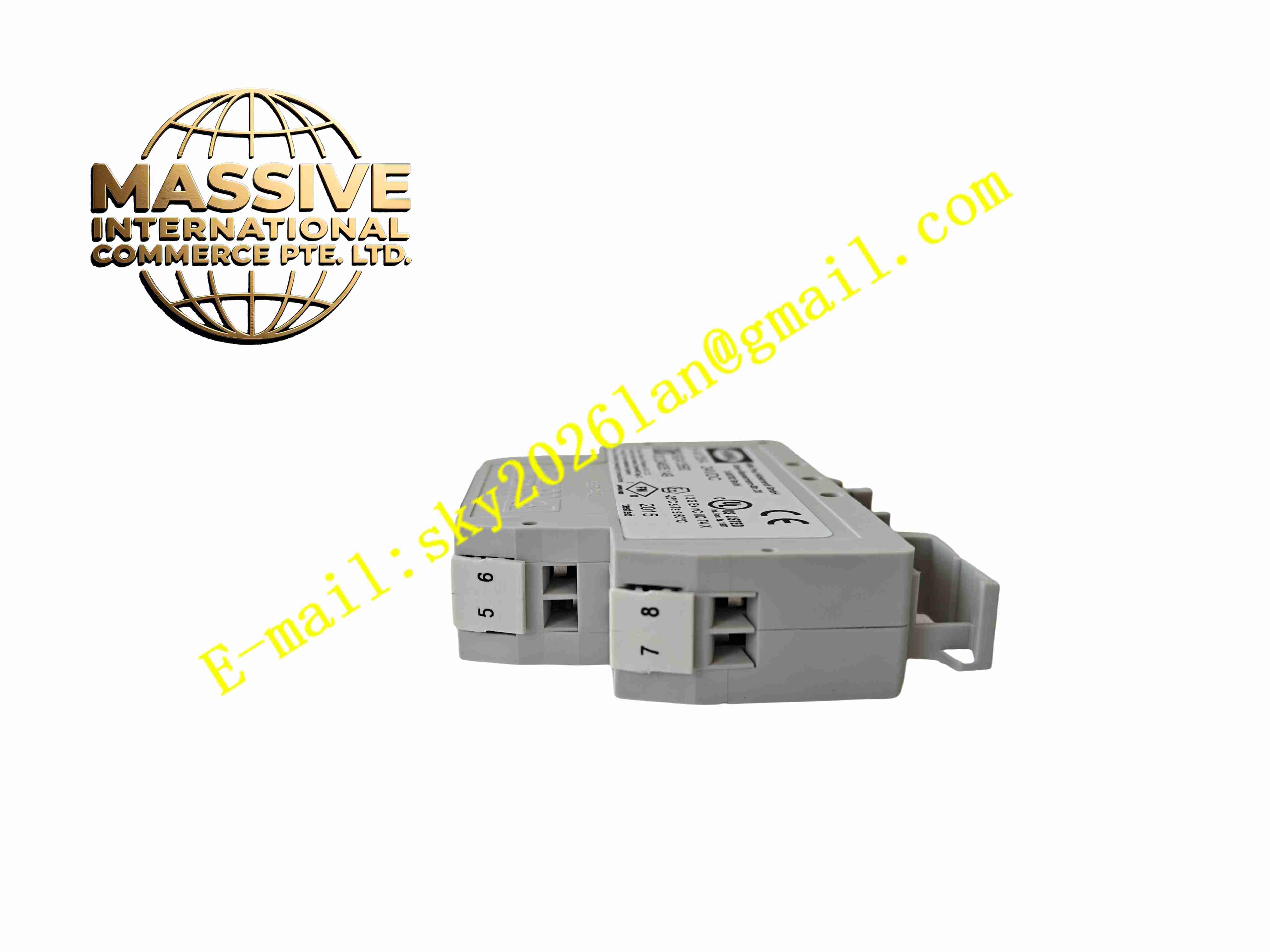
Description
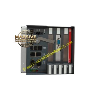
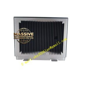
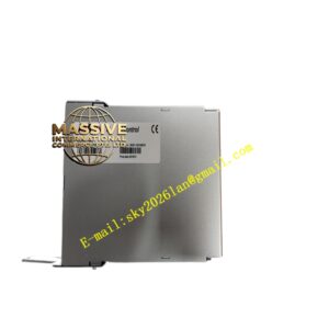
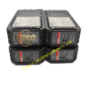
HIMA H4135A 992413560
Technical Specifications
- Product Type: SIL3 safety relay module
- Power Supply: 24 V DC
- Input Signal: 24 V DC safety enable signal
- Output Contact Rating: 10 A @ 250 V AC
- Safety Certification: IEC 61508 SIL3, EN ISO 13849 PL e Category 4
- Response Time: Less than 20 ms
- Diagnostic Functions: Contact welding detection, wire break detection, short circuit detection
- Protection Rating: IP20
- Operating Temperature: -20 °C to +60 °C
- Relative Humidity: 5 % to 95 %, non-condensing
- Mounting: Standard 35 mm DIN rail mounting
- Net Weight: 0.25 kg
Functional Features
- SIL3 / PL e high safety integrity level for process and machinery safety interlock loops.
- Force-guided safety relay contacts ensure positive contact separation under fault conditions.
- Redundant internal safety circuit architecture for fault tolerant operation.
- Built-in diagnostic detects contact welding, wire break and short circuit on input and output loops.
- Fast response time ensures rapid safe shutdown upon safety trip trigger.
- LED indicators show power status, safety channel state and fault alarm.
- Reverse polarity and overvoltage protection safeguards internal circuit from power wiring error.
- Compact DIN rail housing saves cabinet installation space.
- Manual reset function locks safety trip state until fault clearance and operator reset.
- Continuous self-test verifies internal relay and diagnostic circuit integrity during operation.
Application Scenarios
- Petrochemical plant ESD emergency shutdown safety interlock
- Boiler burner management safety fuel valve control
- Machine tool safety gate and emergency stop safety circuit
- Offshore platform fire and gas safety system relay output
- Power plant turbine protection safety contactor control
Material Composition
- Housing: Flame-retardant green polycarbonate plastic enclosure
- Main PCB: FR4 printed circuit board with conformal coating
- Safety components: Force-guided safety electromagnetic relays
- Protection components: Surge suppression diodes and current limiting resistors
- Terminal blocks: Tin-plated copper alloy screw terminals
- Isolation components: Optocoupler isolation chips for input channels
Structural Characteristics
- Slim single width DIN rail plastic enclosure.
- Front panel LED indicators for power, safety status and fault.
- Rear screw terminal blocks for safety input, power supply and safety output wiring.
- Internal dual redundant safety circuit architecture for SIL3 compliance.
- Force-guided relay mechanical linkage prevents independent contact movement in case of contact welding.
- Passive convection cooling without fan components.
Working Principle 24 V DC safety enable signal enters H4135A safety input terminals. When safety conditions are satisfied, internal redundant safety relays energise and close force-guided output contacts to supply power to downstream safety contactor. If safety input signal is removed or diagnostic circuit detects contact welding or wiring fault, safety relays de-energise immediately, force-guided contacts open and cut power to safety load. Trip state latches and requires manual reset after fault elimination. LED indicators display fault type for maintenance.
Installation Requirements
- Mount H4135A on 35 mm DIN rail inside protected control cabinet.
- Use shielded twisted pair cable for safety input wiring.
- Separate safety circuit wiring from high power motor and power cables.
- Complete protective earth connection to cabinet ground bar.
- Use force-guided safety contactor in downstream safety circuit.
- Perform safety function test and fault simulation test after wiring completion.
- Verify contact wiring polarity and continuity.
Usage Notes
- Do not bypass safety input circuit for test operation.
- Use only contact loads within rated contact specification.
- Keep cabinet dry and free of conductive dust and corrosive gas.
- Execute periodic SIL proof test according to safety system maintenance schedule.
- Disconnect power before modifying safety wiring.
- Use anti-static wristband when handling spare module.
- Replace module immediately when permanent safety relay or diagnostic fault occurs.