



Description
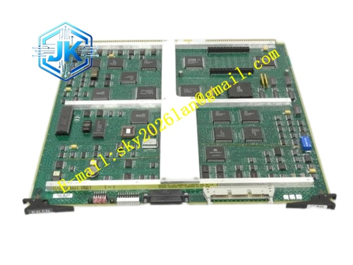
Honeywell 51199847-100
Technical Specifications Input Power: 24V DC Distributed Power Rails: 5V DC, 12V DC, -12V DC Power Consumption: 4.9W Operating Temperature Range: 0℃ to 65℃ Storage Temperature Range: -40℃ to 85℃ Isolation Withstand Voltage: 1500V AC Relative Humidity: 5% to 95%, non-condensing Supervision Sampling Rate: 100 samples per second
Functional Features It integrates multi-stage LC filter circuits to suppress power ripple and high-frequency noise. It implements independent overvoltage, undervoltage and overcurrent detection for each power rail. It generates power good enable signal for all functional modules in HPM rack. It stores power alarm threshold parameters in non-volatile memory. It uploads real-time power status and fault events to HPM diagnostic console. It supports bumpless switchover signal coordination for redundant dual power supply configuration.
Application Scenarios Power distribution supervision for HPM main control racks in petrochemical and chemical plants. Redundant power signal coordination for safety interlock HPM controllers. Replacement and spare stocking for aging power interface boards of legacy TPS HPM cabinets. Power quality monitoring for control racks installed in areas with unstable grid power supply.
Performance Parameters Voltage Sampling Accuracy: ±0.03V Over-current Protection Response Time: ≤2ms Power Rail Ripple Suppression Ratio: 92% Fault Event Storage Capacity: 2000 power alarm records
Material Composition PCB Substrate: Thick copper high-TG FR-4 multi-layer power board, separated power plane and signal plane Precision voltage sampling and current sensing chips LC filter inductors and high-frequency low-ESR capacitors Signal isolation optocoupler chips Gold-plated back edge fingers Cold-rolled steel mounting bracket with electrostatic spray coating
Structural Features Standard pluggable board structure, installed in dedicated power interface slot of HPM rack. Internal power traces adopt widened copper foil layout to reduce temperature rise under full load. Power circuit and diagnostic signal circuit are separated by isolation barrier. Sampling components are arranged close to power output terminals to reduce sampling error. Board surface adopts conformal coating for protection against dust and corrosive gas.
Working Principle 24V DC input power enters the board through backplane terminals. The filter circuit removes transient voltage spikes and high-frequency noise. The power distribution circuit divides raw power into multiple stable rails for HPM internal modules. The sampling circuit continuously measures voltage and current value of each rail. When measured value exceeds preset threshold, the supervision circuit triggers fault flag and stops power good signal output. The board transmits fault timestamp and power status data to HPM main processor via backplane signal bus.
Installation Requirements Insert the board vertically into the dedicated power interface slot of HPM rack and lock the fixing screw. Check 24V DC input polarity before rack power supply switch-on. Download alarm threshold parameters from Control Builder software after power-on. Verify real-time power reading on the HPM diagnostic display page.
Precautions Release static electricity before plugging the board to protect sampling and signal chips. Reverse polarity of 24V input causes immediate damage to internal filter and sampling circuits. Dust accumulation on board surface blocks heat dissipation and triggers false over-temperature alarm. Redundant HPM rack requires two identical power interface boards for normal switchover function. Do not modify internal circuit components without engineering authorization.







