



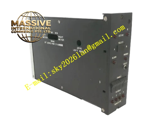
Description
Honeywell 51400712-100
Technical Specifications
- Backplane Interface: TDC3000 proprietary backplane bus
- Remote I/O Link: TDC3000 dedicated serial I/O link bus
- Power Supply: 5VDC and 12VDC from rack backplane
- Operating Ambient Temperature: 0°C to +60°C
- Storage Temperature: -40°C to +85°C
- Relative Humidity: 5% to 90% RH non-condensing
- Mounting Type: Plug-in slot installation on TDC3000 main rack
- Certification: UL, CE, RoHS
Functional Features It cyclically polls all connected remote I/O subracks on the I/O link bus. It collects analog input, digital input and output status data from remote I/O modules. It forwards control output commands from main control processor to remote I/O channels. It detects remote bus short circuit, wiring breakage and remote module offline fault. It carries built-in overcurrent protection for remote I/O link bus. It uploads remote I/O diagnostic information to TDC3000 operator station. It provides front panel LED indicators for bus active, communication and fault status. It supports hot swap replacement in non-critical rack configuration. It supports remote I/O channel configuration and point mapping from TDC3000 engineering workstation.
Application Scenarios Large petrochemical plant TDC3000 remote I/O expansion rack Refinery remote field signal collection cabinet Chemical plant distributed I/O subrack interface Power plant boiler remote measurement and control rack Natural gas compression station remote I/O signal gateway
Performance Parameters
- Remote I/O Link Communication Speed: 500 kbps
- Mean Time Between Failures: 780000 hours
- Isolation Rating: 1500VAC between remote bus and main logic circuit
- Insulation Resistance: Greater than 1000 MΩ
- ESD Immunity: 8kV contact discharge
Material Composition FR4 flame retardant conformal coated multilayer PCB Serial communication controller chip Isolation transformer and optocoupler isolation components Overcurrent and short circuit protection circuit TVS surge suppression components Gold plated edge connector for rack backplane Metal front panel with extraction handle and LED indicators Pluggable terminal block for remote I/O link bus cable
Structural Features Standard paddle card form factor. Front panel integrates remote bus terminal block and group LED indicators plus extraction handle. Rear gold plated edge connector mates with rack backplane power and control bus. Internal circuit provides complete electrical isolation between remote I/O link bus and main rack logic circuit. Anti-key notch prevents reverse insertion into rack slot. Locking clip secures module firmly after installation. Independent current limiting circuit protects remote bus from overload damage.
Working Principle After power on, module initializes remote serial bus communication and polls all connected remote I/O modules cyclically. It reads field measurement value and contact status from remote I/O modules, packages data and transmits to main control processor via backplane bus. It receives control output command from main control processor and sends command to target remote I/O channel. When short circuit or communication timeout is detected on remote bus, protection circuit cuts off bus output and fault alarm is uploaded to operator station.
Installation Requirements Wear anti-static wrist strap before inserting module into vacant main rack slot. Lock extraction handle after alignment. Connect shielded twisted pair remote bus cable to corresponding terminal block. Install bus terminator resistor at two ends of remote bus trunk. Configure remote I/O point mapping and channel parameters in engineering workstation. Power on rack and verify online status of remote I/O modules. Separate remote bus cable from high voltage AC power cable in wiring duct.
Usage Notes Remote bus terminator resistor must be installed at both ends of trunk cable. Keep shield wire single point grounding. Check bus load current before adding new remote I/O subrack. Do not apply external voltage to remote bus terminals. Replace module when bus communication circuit is damaged.







