



Description
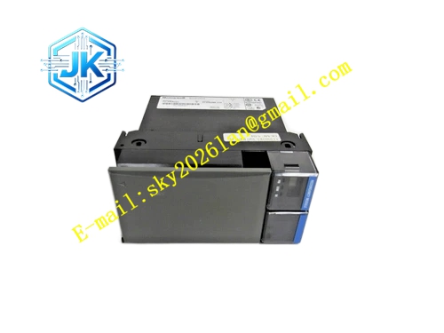
Honeywell 51309288-225
Technical Specifications Redundancy Sync Interface: High-speed differential dedicated sync bus Synchronization Rate: 12Mbps Backplane Interface: HPM internal main backplane bus Power Supply: 5V DC Power Consumption: 7.9W Operating Temperature Range: 0℃ to 65℃ Storage Temperature Range: -40℃ to 85℃ Isolation Withstand Voltage: 1500V AC Relative Humidity: 5% to 95%, non-condensing
Functional Features It executes real-time mirror synchronization of control logic, setpoints, tuning parameters and alarm status between primary and standby HPM. It carries out continuous state comparison and deviation detection between two controllers. It triggers automatic bumpless switchover when primary controller fault is detected. It supports hot swap operation of single module in redundant HPM rack. It stores redundancy configuration and fault log data in non-volatile memory. It uploads synchronization deviation, sync link fault and controller switchover events to the DCS diagnostic system. It supports manual primary/standby switch command from operator station.
Application Scenarios Redundancy synchronization for critical HPM controllers in ESD and safety interlock systems. Fault-tolerant control configuration for reactor, cracking furnace and main distillation unit HPM controllers. Replacement and upgrade of old revision redundancy modules in legacy TPS HPM redundant racks. High-reliability continuous control loops for petrochemical, power and natural gas process plants.
Performance Parameters State Synchronization Latency: ≤35μs Controller Switchover Time: ≤5ms State Deviation Detection Resolution: 1 bit Fault Log Storage Capacity: 300 switchover and sync fault records
Material Composition PCB Substrate: High-TG FR-4 multi-layer board with differential equal-length trace layout High-speed differential synchronization FPGA chip Data buffering SRAM chip State comparison logic chip Gold-plated back edge fingers Gold-plated sync bus terminal contacts Cold-rolled steel front panel with electrostatic spray coating
Structural Features Standard European pluggable card structure, installed in dedicated redundancy slot of paired HPM rack. Front panel is equipped with run indicator light, sync normal indicator light, primary status indicator light and fault indicator light. Dedicated differential sync bus terminals are arranged on the side panel for cable connection between primary and standby HPM. High-speed differential signal area adopts independent shielding layer to suppress electromagnetic interference. Power circuit and synchronization signal circuit are separated to reduce cross crosstalk.
Working Principle The module installed on primary HPM continuously reads real-time control state, I/O data and internal variable from primary controller through backplane bus. It packages state data into high-speed differential frames and transmits frames to the redundancy module on standby HPM via dedicated sync cable. The standby redundancy module receives data and writes all state data into standby controller memory. The two modules compare state data continuously. When primary controller fails or sync deviation exceeds threshold, the module triggers switchover signal, standby controller switches to primary role and takes over all control output without bumping the process loop. It records switchover event and fault time stamp and uploads alarm information to the DCS system.
Installation Requirements Insert one module into the dedicated redundancy slot of primary HPM rack and the second module into standby HPM rack. Connect the two modules with dedicated shielded differential synchronization cable following wiring marking. Tighten backplane fixing screws of both modules. Download HPM redundancy pair configuration from Control Builder software after power on. Verify synchronization status and manual switchover function on the HPM redundancy diagnostic screen.
Precautions Release static electricity before plugging the module to protect high-speed synchronization FPGA chip. The dedicated sync cable cannot be replaced with ordinary twisted pair cable. Do not cut off the sync cable during running of redundant HPM pair, which causes loss of synchronization and switchover failure. Firmware version of the two redundancy modules in one pair must be identical. Regular inspection of sync cable tightness and shielding integrity is required.







