



Description
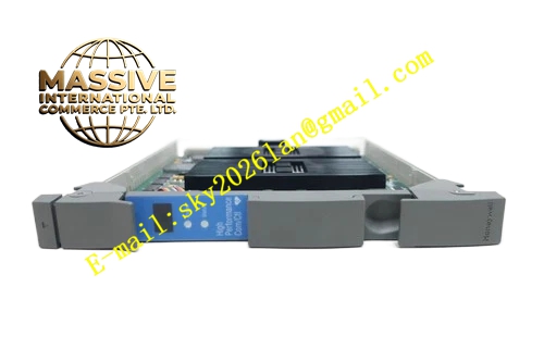
HONEYWELL 51402625-150
Technical Specifications Backplane power supply; High speed I/O link bus interface; Hardware data check circuit; Communication fault detection; Rack plug-in structure; Compatible with TDC3000 controller rack.
Functional Features Establish high speed communication link between controller and I/O submodules; Forward control command from controller to each I/O subcard; Collect field I/O data and upload to controller; Verify data packet integrity; Monitor I/O link bus status; Report communication interruption and data error to controller.
Application Scenarios TDC3000 controller rack in petrochemical and thermal power plant; Internal communication between controller and I/O submodules; Process control station with mass I/O points.
Performance Parameters Operating temperature 0℃ to 60℃; Humidity 5% to 95%, non-condensing; Stable high speed data transmission; Meet industrial control EMC standard.
Material Composition FR-4 multilayer printed circuit board; Gold-plated backplane gold finger; Communication processing chip; Filter resistors and capacitors; Anti-static plastic panel.
Structural Features Rack plug-in card; Front panel equipped with communication and fault LED indicators; Rear gold fingers connect rack backplane bus; Anti-reverse insertion positioning notch; Model and revision printed on panel.
Working Principle The module acts as communication bridge between controller and I/O subcards. It receives control instruction from controller, packages and distributes command to corresponding I/O submodules. It receives collected field data from I/O subcards, verifies data validity and transmits to controller. The diagnostic circuit continuously monitors bus communication quality and triggers alarm when communication failure occurs.
Installation Requirements Wear anti-static wrist strap during disassembly and assembly; Insert card fully into designated rack slot and lock fixing screw; Cabinet protective ground is complete; Verify hardware version matches controller firmware.
Precautions for Use Prohibit hot swapping of module; Check I/O link bus cable when communication fault appears; Keep module away from high-power motor and inverter; Prevent dust accumulation on card surface.







