



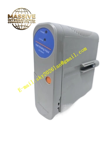
Description
Honeywell 8C-PAIHA1
Technical Specifications
- Channel count: 16 analog input channels
- Signal type: 4–20 mA DC current loop
- HART support: HART 5, full master communication mode
- Resolution: 16-bit ADC
- Channel isolation: 2500 VAC per channel
- Loop power supply: 24 V DC, 20 mA per channel
- Backplane interface: C300 I/O subrack high-speed serial bus
- Operating temperature: 0 °C to +60 °C
- Hot swap support: Online card replacement without subrack shutdown
Functional Features Per-channel 2500 VAC electrical isolation, blocks field high voltage from entering the control backplane. HART master communication, reads smart transmitter diagnostics, process variable range and device configuration without extra handheld communicator tools. Independent 24 V loop power per channel, eliminates external transmitter power supplies. Per-channel wire break and short circuit diagnosis, triggers channel fault alarm on open circuit or overcurrent. Digital input filter, smooths sampled values and suppresses field electromagnetic noise. On-board LEDs indicate card power, communication and overall fault status. Configurable channel range scaling via C300 Control Builder software.
Application Scenarios Large-scale refinery process temperature, pressure and flow signal acquisition Chemical plant smart HART transmitter network integration Power generation unit analog measurement loops Spare part replacement for high-density analog input card faults High-channel-count I/O retrofits for aging C300 systems
Performance Parameters
- Conversion accuracy: ±0.1% full scale
- Full channel update rate: 10 ms
- Common mode rejection ratio: ≥90 dB
- Wire break detection response: ≤200 ms
- HART communication update rate: 500 ms per channel
- Mean time between failures: 700,000 hours
Material Composition FR4 low-noise flame retardant PCB substrate 16-bit multiplexed ADC chip HART modem integrated circuit Channel isolation optocoupler array Precision metal film sampling resistors TVS surge protection diodes Gold-plated backplane edge fingers UL94 V0 flame retardant plastic front panel
Structural Features Standard C300 I/O card form factor, inserts directly into dedicated subrack slots. Front detachable field terminal block arranges 16 channel wiring points. Physical isolation barrier separates field signal side and backplane logic side. Equal-length analog traces minimize channel crosstalk. Anti-keying notch prevents insertion into non-analog slots. Front panel LEDs display card run and fault status.
Working Principle Field transmitter signals connect to the front terminal block. On-board 24 V loop supply powers the connected smart transmitter. 4–20 mA current passes through precision sampling resistors to the multiplexed 16-bit ADC, converting analog values to digital counts. The HART modem superimposes digital communication signals on the 4–20 mA loop, exchanging configuration and diagnostic data with the smart transmitter. Isolation optocouplers provide full electrical separation between field side and system backplane. Converted engineering values are packaged into serial bus frames, transmitted to the C300 controller over the I/O subrack backplane.
Installation Requirements Power off the subrack before card insertion, press evenly until gold fingers are fully seated. Wire field transmitters to labeled channel terminals, observe loop polarity. Configure HART device address and channel scaling in Control Builder software. Check channel values and HART communication status after power-up, confirm all transmitters are detected.
Usage Notes Never apply AC high voltage to input terminals, this destroys channel isolation optocouplers. HART communication requires shielded twisted pair cable, routed separately from high-voltage power trays. Channel overcurrent triggers protection; auto-recovery occurs after fault removal. Do not mix HART and non-HART transmitter configuration across incorrectly mapped channels; HART commands apply only to supported devices.







