



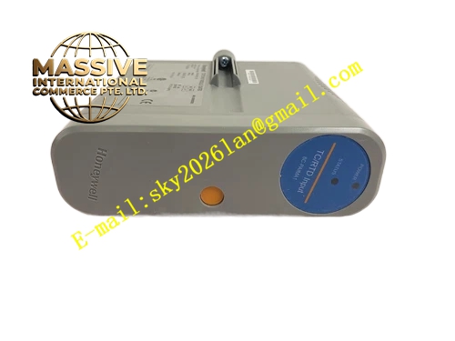
Description
Honeywell 8C-PAIMA1
Technical Specifications
- Channel count: 8 analog input channels
- Signal types: 4–20 mA DC, 1–5 V DC
- Resolution: 16-bit ADC
- Channel isolation: 500 VAC between field group and backplane
- Loop power supply: 24 V DC, 20 mA per channel
- Backplane interface: C300 I/O subrack bus
- Operating temperature: 0 °C to +60 °C
- Hot swap support: Online card replacement
Functional Features Supports both current loop and voltage signal inputs, software configurable per channel. Group isolation between field wiring and backplane, blocks common field surge events. Per-channel wire break diagnosis, triggers fault flag on open transmitter circuit. Digital filter reduces signal noise from field electromagnetic interference. On-board LEDs indicate card power, communication and fault status. Software-configurable input range and engineering unit scaling.
Application Scenarios General process temperature, pressure and level measurement loops Small production unit analog I/O integration Spare part replacement for standard analog input card faults C300 system I/O expansion for small process units
Performance Parameters
- Conversion accuracy: ±0.1% full scale
- Full channel update rate: 20 ms
- Common mode rejection ratio: ≥85 dB
- Input impedance: 100 kΩ for voltage input, 250 Ω for current input
- Mean time between failures: 600,000 hours
Material Composition FR4 low-noise PCB substrate 16-bit ADC chip Instrumentation amplifier array Group isolation optocouplers TVS surge protection diodes Gold-plated backplane edge fingers Flame retardant plastic front panel
Structural Features Standard C300 I/O card form factor. Front detachable terminal block for 8 channel wiring. Isolation barrier separates field side and backplane side. Anti-keying notch prevents mis-slot insertion. Front status LEDs for card run and fault.
Working Principle Field signals connect to input terminals, routed to the instrumentation amplifier. The amplified signal feeds the 16-bit ADC, converting analog voltage or current to digital values. Group isolation optocouplers separate field side from backplane logic. Wire break detection monitors loop current; open circuit triggers a channel fault flag. Converted values are packaged into bus frames, sent to the C300 controller over the subrack backplane.
Installation Requirements Insert the card into a dedicated analog input subrack slot, press fully seated. Wire field sensors to labeled terminals, configure input type per channel in Control Builder. Verify measured values read correctly after power-up. Check channel fault status, confirm no open circuit alarms.
Usage Notes Never exceed rated input voltage on voltage channels, overvoltage destroys the ADC input. Shielded cable for field sensor wiring reduces EMI-induced signal noise. Group isolation does not replace per-channel isolation for high-voltage surge applications. Terminal blocks must be fully locked; loose connections cause intermittent channel dropout.







