



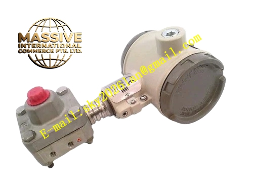
Description
Honeywell 8C-PDILA1
Technical Specifications
- Channel count: 32 digital input channels
- Supported signals: 24 V DC active switch, dry contact
- Channel isolation: 500 VAC per channel
- Input threshold: 15 V DC minimum ON, 5 V DC maximum OFF
- Debounce time: Software configurable 1 ms to 20 ms per channel
- Backplane interface: C300 I/O subrack bus
- Operating temperature: 0 °C to +60 °C
- Hot swap support: Online card replacement
Functional Features Per-channel optocoupler isolation, blocks field surge voltage from the backplane. Software-adjustable debounce filter, eliminates mechanical contact bounce. Per-channel open wire diagnosis, triggers fault alarm on broken switch wiring. Per-channel LED indicates real-time input state. Group fault flag reports card communication and power abnormality. Configurable channel polarity for sink or source input devices.
Application Scenarios Valve position limit switch feedback collection Pump and motor auxiliary contact status monitoring Pressure and level switch interlock signal acquisition Strong-interference industrial discrete input loops Spare part replacement for isolated digital input card faults
Performance Parameters
- Input response time: Matches configured debounce time
- Channel crosstalk attenuation: ≥-60 dB
- Wire break detection response: ≤180 ms
- Insulation resistance: ≥1000 MΩ
- Mean time between failures: 650,000 hours
Material Composition FR4 flame retardant PCB substrate Channel isolation optocoupler array RC debounce filter components TVS protection diodes Gold-plated backplane edge fingers UL94 V0 plastic front panel
Structural Features Standard C300 I/O card form factor. Front detachable terminal block arranges 32 channel wiring points. Isolation barrier separates field input side and backplane logic side. Per-channel LEDs aligned with corresponding terminal positions. Anti-keying notch prevents mis-slot insertion.
Working Principle Field 24 V DC switch contacts connect to input terminals. Optocouplers isolate field signals, converting contact state to logic level for the on-board sampling circuit. The debounce timer filters fast transient state changes caused by mechanical contact bounce. Sampled channel states are packaged into bus frames, transmitted to the C300 controller. Open wire detection monitors loop current; broken switch wiring triggers a channel fault flag.
Installation Requirements Insert the card into a dedicated digital input subrack slot. Wire field switches to labeled channel terminals. Configure debounce time per channel in Control Builder software. Verify channel state changes synchronously with field switch action after power-up.
Usage Notes Never connect AC high voltage to digital input terminals, this destroys optocoupler isolators. Debounce time set too short causes unstable status reading for aging mechanical switches. Long field cable runs increase induced noise and false triggering risk; use shielded cable. Channel groups must not exceed rated isolation voltage, common-mode surges require additional external protection.







