



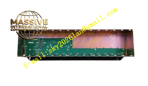
Description
Honeywell 900R12-0200
Technical Specifications
- Channel Quantity: 12 relay output channels
- Contact Type: Form A normally open dry contact
- Maximum Contact Rating: 250 VAC, 3 A per channel
- Isolation: Full galvanic isolation between relay coil and contact circuit
- Working Temperature: 0°C to +60°C
- Storage Temperature: -40°C to +85°C
- Humidity: 5% to 90% RH non-condensing
- Module Supply: 24VDC from rack backplane
- Power Consumption: 4.2 W maximum
- Mounting: HC900 standard rack plug-in
- Certification: UL, C-UL, CE
Functional Features Each relay channel provides independent dry contact output. No common power supply required for field load circuit. Each channel has status LED indicator. It supports hot swap operation. It supports configurable fault safe state for each channel. It detects relay coil driving fault and reports fault code to controller. It can switch AC and DC mixed load circuits. It supports configuration via Process Control Designer software.
Application Scenarios Motor start stop interlock circuit switching Fire and gas alarm system relay interlock High voltage auxiliary circuit control Boiler burner interlock safety circuit Remote damper actuator control HC900 control system spare replacement
Performance Parameters
- Relay Contact Life: 100000 operations at rated load
- Insulation Resistance between coil and contact: above 1000 MΩ
- Contact Switching Response Time: less than 10ms
- Mean Time Between Failures: 760000 hours
- Dielectric Withstand Voltage: 1500 VAC between coil and contact
Material Composition FR4 flame retardant PCB Miniature industrial electromagnetic relays Relay drive transistors TVS surge protection components ABS flame retardant front panel with channel marking Tri-color LED indicators Metal rack locking buckle
Structural Features Standard HC900 plug-in module form factor. Front panel contains 12 channel LED indicators and power/fault indicator. Side anti-misalignment notch prevents reverse insertion. Rear gold finger contacts connect to rack backplane. Wiring terminal area is separated from relay coil electronic zone. Lock clip fixes the module on rack.
Working Principle HC900 controller sends switch command through backplane bus to the module drive circuit. Drive circuit energizes or de-energizes the relay coil. The relay contact closes or opens to switch external field circuit. The module monitors coil driving status continuously. When coil drive failure occurs, the module triggers fault alarm and upload fault information to controller.
Installation Requirements Cut off rack power before module insertion. Align notch and insert into empty slot, lock buckle. Connect field external load wiring to relay contact terminals. Configure fault safe state and output logic in configuration software. Power on rack and test each relay action. Do not exceed contact voltage and current rating.
Usage Notes Do not exceed 250VAC and 3A contact rating for each channel. Inductive AC load must add RC absorption circuit at contact terminal. Relay contact will wear after repeated operation, replace module when contact degradation appears. Static protection required during replacement. Do not use this module in explosive atmosphere without additional explosion proof housing.







