



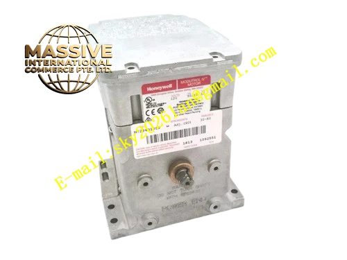
Description
Honeywell M7284Q1106
Technical Specifications
- Power Supply: 24VAC, 50/60Hz
- Control Signal: 4mA to 20mA DC modulating input
- Rated Torque: 150 lb-in
- Adjustable Stroke Range: 90° to 160°
- Running Time: 30 seconds for 90° stroke
- Auxiliary Switch Quantity: 2 independent SPDT auxiliary switches
- Auxiliary Switch Contact Rating: 250VAC, 3A resistive load
- Working Ambient Temperature: -40°C to +67°C
- Storage Temperature: -40°C to +85°C
- Protection Grade: NEMA 3, IP54
- Mounting Method: Foot mounting bracket installation
- Certification: UL, C-UL, CE, FM
Functional Features Two independent auxiliary switches support adjustable trigger position through built-in cam. It supports field adjustable zero point and span calibration for 4-20mA control signal. Dual ended slotted and tapped output shaft for flexible linkage installation. It maintains constant torque within full voltage range. It has integral junction box with quick connect wiring terminals. It supports adapter bracket to replace old generation Modutrol motors. It keeps shaft position unchanged when power supply is interrupted. It supports mechanical linkage for multiple dampers and valves.
Application Scenarios Large industrial boiler gas valve modulating control with position limit interlock Refinery process heater air damper adjustment and limit feedback Oil burner fuel regulating valve control with upper and lower position alarm Thermal furnace air-fuel ratio control system Combustion safety interlock system with damper position feedback Burner control cabinet modulating actuator spare replacement
Performance Parameters
- Positioning Accuracy: ±1% of full stroke
- Mean Time Between Failures: 740000 hours
- Mechanical Shaft Life: 100000 full stroke cycles
- Auxiliary Switch Mechanical Life: 100000 operations at rated load
- Input Signal Impedance: 250Ω for 4-20mA signal
- Operating Noise: Less than 55dB
Material Composition Die cast aluminum alloy housing Brushless servo drive motor Precision grease sealed gear reduction assembly Potentiometer position feedback sensor Dual SPDT auxiliary micro switches Adjustable cam set for auxiliary switch trigger Signal conditioning PCB circuit Quick connect terminal block Steel mounting crank arm and bracket Silicone rubber sealing gasket
Structural Features Rectangular die cast aluminum housing with integrated wiring junction box. Dual ended output shaft for crank arm installation. Internal cam mechanism for auxiliary switch position setting. Removable front cover for zero, span and cam position adjustment. Foot mounting base with fixed installation holes. Internal position feedback potentiometer tracks real rotation angle. Sealing gasket between housing and cover prevents dust and splash water ingress.
Working Principle 4-20mA command signal enters actuator control circuit. The circuit compares command signal and potentiometer feedback signal. Servo motor drives gear set and output shaft to rotate until feedback value matches target value. When shaft rotates to preset trigger angle, the cam pushes micro switch and changes auxiliary switch contact state. When power supply cuts off, the gear set locks shaft at current position without automatic reset.
Installation Requirements Fix M7284Q1106 on foot mounting bracket and connect crank arm linkage to valve or damper. Wire 24VAC power supply, 4-20mA control signal and auxiliary switch wiring to junction box terminals. Adjust zero point, span and auxiliary switch trigger cam position after mechanical installation. Power on actuator and test full stroke movement and switch action. Install actuator upright to satisfy NEMA 3 protection requirement.
Usage Notes This model has no spring return mechanism, independent safety shutdown valve is required for burner safety logic. Do not exceed rated 150 lb-in torque load on output shaft. Adjust auxiliary switch cam carefully to avoid contact damage during stroke movement. Keep actuator away from direct high temperature radiation of flame. Do not apply external impact force to output shaft.







