



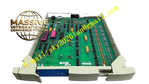
Description
Honeywell MC-PDIXO2
Technical Specifications
- Channel Configuration: Digital input and digital output mixed channels
- Signal Type: 24VDC sinking / sourcing discrete signal
- Rated Input Voltage: 18VDC to 30VDC
- Rated Output Load: 0.5A per channel
- Communication Interface: Redundant ControlNet bus
- Working Ambient Temperature: 0°C to +60°C
- Storage Temperature: -40°C to +85°C
- Relative Humidity: 5% to 90% RH non-condensing
- Isolation Rating: 1500VAC field to logic isolation
- Mounting Method: Plug-in installation on CIOM-A chassis slot
- Certification: TÜV, UL, C-UL, CE
Functional Features Each digital input channel supports open circuit and short circuit fault detection. Each digital output channel supports overload and short circuit protection. It supports configurable input debounce time for mechanical contact switches. It uploads channel status and diagnostic fault code to Experion PKS controller via redundant ControlNet bus. It supports hot swap replacement without powering down the whole CIOM-A chassis. It has LED status indicator for power, module fault and each channel. It supports configurable safe state for output channels when communication fails.
Application Scenarios Valve limit switch feedback signal collection and solenoid valve output control Pump and fan running feedback and start-stop discrete output Chemical plant interlock contact signal acquisition and relay drive Refinery auxiliary equipment discrete status monitoring and control Experion PKS CIOM-A mixed discrete I/O spare module replacement
Performance Parameters
- Input Response Delay: Less than 0.3ms after debounce
- Insulation Resistance: Greater than 1000 MΩ
- Mean Time Between Failures: 870000 hours
- Diagnostic Coverage: Greater than 93% of safety related faults
- ESD Immunity: 8kV contact discharge
Material Composition FR4 flame retardant PCB substrate High speed optocoupler isolation array TVS surge suppression diodes Current sampling resistors Output power driving MOSFET array ABS flame retardant front panel Tri-color LED status indicators Metal locking buckle and gold finger edge connector
Structural Features Standard plug-in CIOM-A module form factor. Front panel integrates LED indicators and module extraction handle. Rear gold finger connector mates with CIOM-A chassis backplane and ControlNet bus. Internal circuit separates field signal zone and ControlNet communication logic zone. Isolation barrier separates field side and internal logic circuit. Locking clip secures module firmly in chassis slot.
Working Principle Field discrete input signal passes optocoupler isolation and sampling circuit, signal status is transmitted to module logic core. Logic core sends input status data to Experion PKS controller through ControlNet bus. Controller sends output command back to module. The driving circuit switches 24VDC power to corresponding output channel. The module continuously monitors output loop current. When overload or short circuit occurs, the module cuts off output and sends fault alarm message.
Installation Requirements Power off the target chassis slot before inserting module. Align anti-misalignment notch and insert into CIOM-A vacant slot, lock the buckle. Connect field wiring to matched terminal assembly. Configure channel input mode, debounce time and output safe state in Experion PKS engineering software. Power on the chassis and verify ControlNet communication and channel status. Separate discrete signal cable from high voltage power cable.
Usage Notes Do not apply AC voltage to any input or output terminal. Inductive load connected to output channel must install surge absorption diode. Static protection wrist strap must be worn during module replacement. Do not exceed rated 0.5A load current per output channel. Verify safe state configuration before commissioning interlock loop.







