



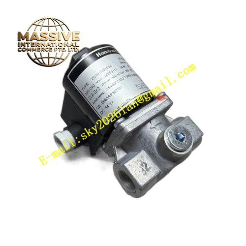
Description
Honeywell VE4020B1145
Technical Specifications
- Valve Type: Normally closed, direct acting solenoid gas valve
- Nominal Diameter: DN20
- Rated Operating Pressure: 360 mbar maximum inlet pressure
- Coil Voltage: 220VAC 50/60Hz
- Valve Body Material: Die cast aluminum alloy
- Seal Material: Nitrile rubber
- Operating Ambient Temperature: -15°C to +60°C
- Protection Class: IP54
- Connection Type: Thread connection
- Certification: CE, AGA, CSA gas safety certification
Functional Features Fast opening and fast closing response to meet burner safety interlock requirement. It provides reliable shutoff when power supply fails. It integrates built-in filter screen to block pipeline impurities and protect sealing surface. It supports one-way gas flow and prevents reverse flow. It has low pressure drop under rated flow condition. It is compatible with Honeywell burner controllers and flame detectors. It supports manual inspection for tightness test. It maintains stable sealing performance under long-term cycle switching. It is resistant to minor gas impurities and moisture inside pipeline.
Application Scenarios Commercial boiler natural gas supply shutoff control Industrial hot air furnace burner gas pipeline safety valve LPG combustion equipment gas interlock system Heat treatment furnace gas burner control loop Packaged burner gas safety cut-off assembly
Performance Parameters
- Opening Response Time: Less than 1 second
- Closing Response Time: Less than 1 second
- Leakage Rate: Zero leakage under rated shutoff pressure
- Service Life: More than 100,000 switching cycles
- Pressure Drop: Low pressure drop at full rated flow
Material Composition Die cast aluminum alloy valve body Nitrile rubber sealing diaphragm and sealing seat Coil winding with high temperature resistant enameled wire Iron core and magnetic armature assembly Stainless steel built-in filter screen Spring steel return spring Plastic coil housing Threaded brass connection port
Structural Features Direct acting solenoid structure without mechanical lever. Coil assembly is mounted on top of valve body and can be replaced separately. Internal built-in filter screen is installed at gas inlet channel. Return spring drives armature and sealing diaphragm to close valve when de-energized. Flow channel is optimized to reduce flow resistance. Coil housing is sealed to prevent dust and moisture intrusion. Threaded inlet and outlet ports support convenient pipeline installation.
Working Principle When coil is energized, electromagnetic force pulls armature upward and lifts sealing diaphragm away from valve seat. Gas channel opens and fuel gas flows through valve body. When power supply is cut off, electromagnetic force disappears. Return spring pushes armature and sealing diaphragm back to valve seat, gas channel closes and gas supply is shut off immediately. Built-in filter intercepts solid impurities in gas pipeline to avoid sealing surface damage. The valve maintains closed state until coil receives energized signal again.
Installation Requirements Install valve on horizontal gas pipeline with coil vertical upward direction. Follow gas flow direction mark on valve body. Install filter before valve inlet if pipeline contains heavy impurities. Use approved gas thread sealant for threaded connection. Complete gas tightness test after installation and before commissioning. Connect coil power wiring to burner controller output contact. Install isolation manual ball valve on upstream and downstream for maintenance. Keep valve away from high temperature radiation of burner flame.
Usage Notes Do not use the valve for corrosive gas, oxygen or liquid medium. Regularly perform gas tightness inspection. Replace sealing diaphragm when leakage occurs. Do not apply voltage different from rated coil voltage. Cut off gas supply and power before disassembling valve. Keep coil housing clean and away from water splash.







