Description
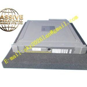
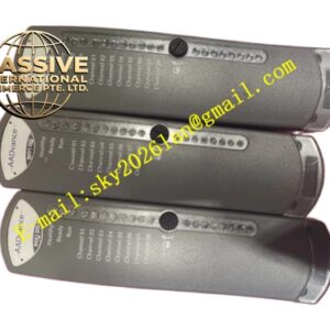
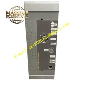
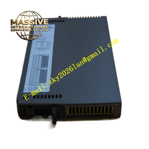
ICS Triplex‑T8480 Digital Input Module
Technical Specifications:
- Input Signal Type: Dry contact / 24 VDC wet contact digital input
- Channel Count: 32 input channels
- Nominal Input Voltage: 24 VDC
- Input On‑state Threshold: Minimum 10 VDC
- Input Off‑state Threshold: Maximum 5 VDC
- Backplane Supply: 24 VDC from rack power unit
- Isolation Rating: 2500 VDC between field input and internal logic circuit
- Operating Temperature: 0 °C ~ +60 °C
- Storage Temperature: −40 °C ~ +85 °C
- Relative Humidity: 5 %‑95 %, non‑condensing
- Vibration Resistance: 2 g (10‑500 Hz)
- Shock Resistance: 15 g, 11 ms
- Net Weight: 0.70 kg
- Certifications: SIL 3, ATEX, IECEx, CE
Functional Features:
- TMR triple‑channel input acquisition, hardware voting eliminates single‑channel failure impact
- Per‑channel LED status indicators for ON / OFF / fault condition
- Built‑in wire breakage detection function for field input circuits
- Real‑time channel diagnostic data upload to main controller
- Hot‑swap compatible within Trusted valid system configuration
- Input filter time configurable to suppress field contact bounce and transient noise
- Supports common positive and common negative field wiring modes
Application Scenarios: Emergency shutdown system contact signal acquisition, fire‑gas system switch input, process interlock status feedback, turbine protection discrete signal collection, chemical plant safety switch monitoring, offshore platform safety instrument system input processing.
Material Composition:
- Module housing: Flame‑retardant composite structural frame
- Circuit substrate: Conformal coated multi‑layer industrial PCB
- Field terminals: Screw‑type locking spring terminals
- Backplane connector: Gold‑plated 96‑pin industrial connector
- Fasteners: Stainless steel anti‑vibration hardware
Structural Characteristics: Standard Trusted rack‑mount module dimension. Front panel holds LED indicator bank and field wiring terminal blocks. Rear side installs 96‑pin backplane mating connector. Internal metal shielding partitions isolate field input circuits and logic circuits. Two side spring latches lock module firmly into rack slots.
Working Principle: Field contact signals feed into three independent input sampling circuits simultaneously. Each channel converts field electrical level into digital logic value. Hardware voting circuit compares three sampled values, outputs consistent valid logic state to main controller. Diagnostic circuits monitor input circuit impedance, identify open‑circuit and abnormal impedance conditions. All diagnostic results transmit to main processor via rack backplane bus.
Installation Requirements:
- Slide module into the designated slot of Trusted system rack.
- Lock both side latches completely to ensure full backplane connector engagement.
- Follow official terminal drawing for field contact wiring. Separate safety signal cables from high‑power cables.
- Connect rack protective earth to plant safety grounding network.
- Configure input filter parameters via system software according to field contact bounce characteristics.
Usage Notes:
- Do not apply voltage exceeding rated range onto input channels. Overvoltage destroys input circuit components.
- Wire breakage detection function requires appropriate loop current. Pure high‑impedance dry contact cannot trigger wire break diagnosis.
- Avoid routing input cables alongside high‑voltage power cables to reduce induced electromagnetic noise.
- Inspect terminal screw tightening torque periodically in high‑vibration working locations.
- Module hot‑swap operation must follow system operation manual procedure.