Description
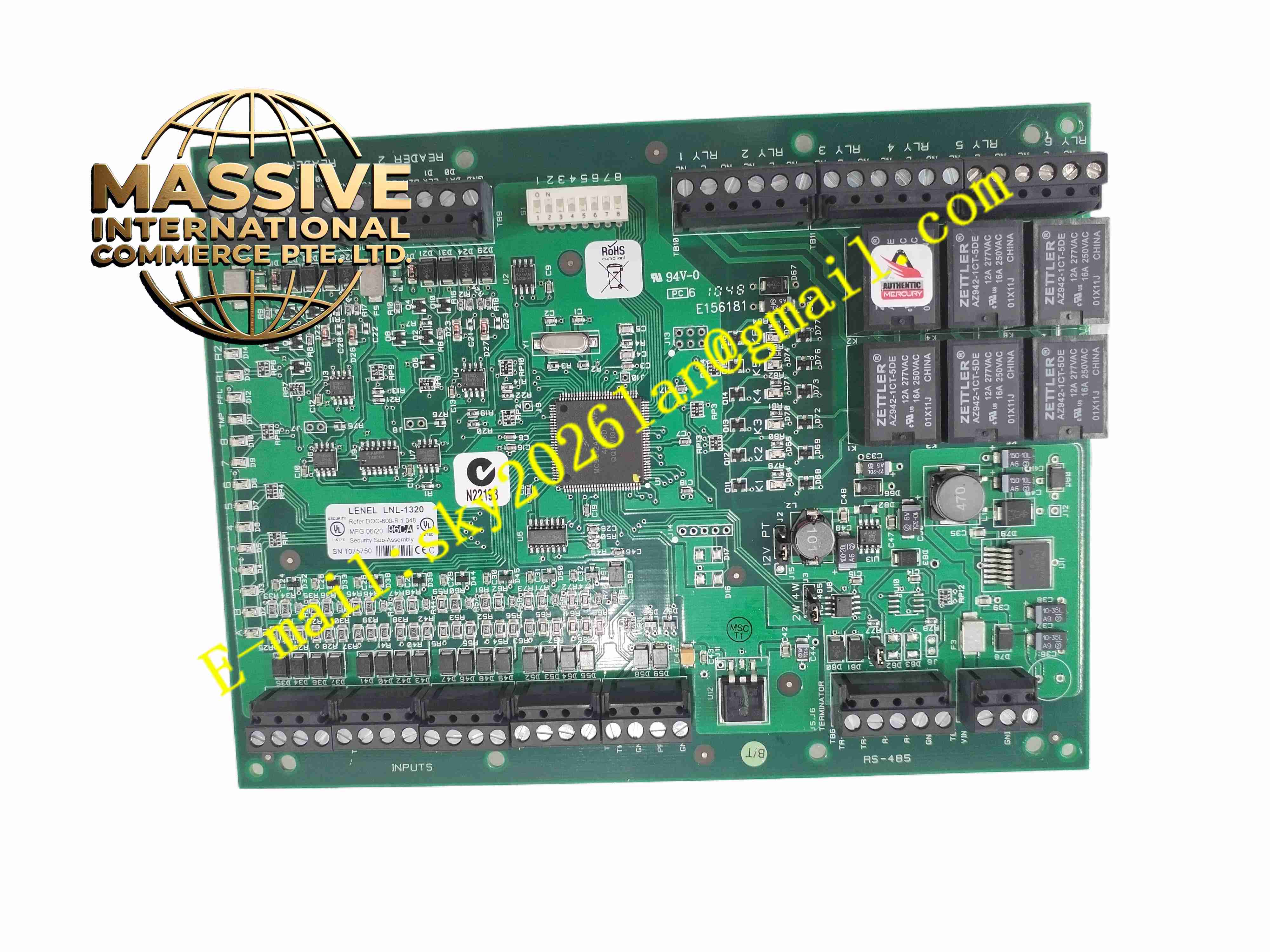
Lenel LNL-1320 Dual Reader Interface Module
Technical Specifications
- Brand: LenelS2
- Product Type: Dual Reader Interface module
- System Compatibility: Lenel OnGuard access control system
- Reader Ports: Supports two readers per module
- Reader Protocols: Wiegand Data1/Data0, Magnetic Clock/Data, and OSDP-capable variants depending on model generation
- Reader Power Output: 12 VDC regulated, up to 300 mA per reader
- Primary Power Input: 12 to 24 VDC ±10%
- Maximum Current Draw: Up to 550 mA at 12 VDC, plus reader current; up to 330 mA at 24 VDC, plus reader current
- Inputs: 8 inputs, supporting supervised and unsupervised circuits
- Outputs: 6 Form-C relay outputs
- Relay Rating: Normally Open 5 A at 30 VDC; Normally Closed 3 A at 30 VDC
- Communication Interface: RS-485 downstream connection to Lenel controller
- Addressing: Individually addressed on the RS-485 network
- Dimensions: Approximately 152 mm W × 203 mm L × 25 mm H
- Weight: Approximately 312 g nominal
- Operating Temperature: 0°C to 70°C
- Storage Temperature: -55°C to 85°C
- Humidity: 5% to 95% RH, non-condensing
- Compliance: FCC Part 15, CE, RoHS, UL 294, UL 1076, CSA/ULC standards
Functional Features
- Dual reader support: Connects two credential readers to one interface module.
- Multiple reader protocols: Supports Wiegand, Magnetic Clock/Data, and OSDP depending on version.
- Eight monitored inputs: Accepts door contacts, request-to-exit sensors, tamper switches, and other alarm inputs.
- Six relay outputs: Drives locks, strikes, maglocks, annunciators, or auxiliary devices.
- Supervised I/O: Supports end-of-line monitoring for improved tamper and fault detection.
- RS-485 networked deployment: Multiple modules can be connected to a Lenel controller over RS-485.
- Offline access support: Readers can support lock/unlock and facility code offline access modes.
- Firmware updatability: Newer variants support firmware updates for continued compatibility.
Application Scenarios
- Office building door access control
- Data center and server room security
- Industrial plant entry control
- Campus perimeter and building access
- Hospital restricted-area monitoring
- Elevator lobby and stairwell access control
Performance Parameters
- Reader Capacity: 2 readers per module
- Input Count: 8 supervised/unsupervised inputs
- Output Count: 6 Form-C relay outputs
- Relay Capacity: 5 A NO / 3 A NC at 30 VDC
- Reader Power: 12 VDC at up to 300 mA per reader
- Communication: RS-485 to Lenel controller
- Operating Temperature: 0°C to 70°C
- Power Input: 12 to 24 VDC ±10%
Material Composition
- Enclosure: Industrial-grade PCB mounted in a protective housing
- Terminal Blocks: Screw terminals for power, I/O, and reader wiring
- Internal Circuitry: RS-485 interface, reader interface logic, input supervision, and relay drivers
- Protection Components: Overcurrent, reverse-polarity, and transient protection circuits
- Status Indicators: LEDs for power, communication, and I/O status
Structural Features
- Compact PCB module: Designed for installation inside a secured control cabinet or enclosure.
- Dedicated reader ports: Two reader interfaces simplify door wiring.
- Supervised I/O terminals: Inputs support end-of-line resistors for fault monitoring.
- Form-C relays: Provide both normally open and normally closed contact options.
- Addressable RS-485 node: Each module has a unique address on the controller bus.
- Modular system integration: Works with Lenel intelligent system controllers and OnGuard software.
Working Principle
The LNL-1320 receives credential data from connected readers through Wiegand, Clock/Data, or OSDP interfaces. It forwards this data to the Lenel controller over RS-485, where access decisions are evaluated. Based on controller commands, the module activates relay outputs to unlock doors or trigger alarms. Input circuits monitor door contacts, tamper switches, and other sensors, reporting status changes back to the controller for logging and alarm handling.
Installation Requirements
- Install inside a locked, dry, and ventilated control cabinet.
- Provide a regulated 12 to 24 VDC power supply with sufficient current capacity.
- Connect readers using the correct protocol and wiring pinout.
- Use shielded cable for reader and RS-485 communication lines.
- Configure end-of-line resistors for supervised inputs where required.
- Assign a unique RS-485 address to each module on the network.
- Verify relay wiring matches the lock type, fail-safe or fail-secure requirements.
Precautions for Use
- Do not exceed the relay contact rating of 5 A NO or 3 A NC at 30 VDC.
- Ensure reader power draw does not exceed 300 mA per reader port.
- Keep RS-485 wiring away from high-voltage power cables.
- Use proper grounding and surge protection for door hardware and long cable runs.
- Confirm firmware and hardware compatibility with the installed OnGuard controller.
- For exact wiring diagrams, supported reader protocols, and model suffix details, refer to the official Lenel LNL-1320 installation guide.