Description
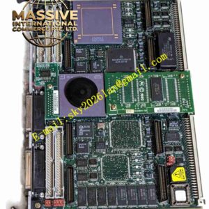
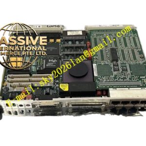
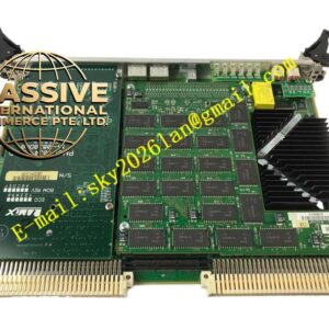
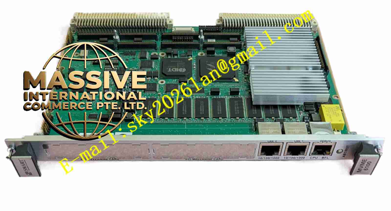
Motorola MVME6100-0171
Technical Specifications
- Processor: 1.267 GHz MPC7457 PowerPC processor with integrated L1 and L2 caches.
- System Memory: 1 GB of ECC-protected DDR DRAM operating at 133 MHz.
- Flash Memory: 128 MB of Intel StrataFlash memory.
- Network Interfaces: Dual 10/100/1000 Mbps Gigabit Ethernet ports.
Functional Features
- High-Speed VME Interface: Utilizes the Tsi148 VME Bridge ASIC to support the 2eSST protocol, delivering up to 320 MB/s of actual bandwidth.
- PMC Expansion: Features two IEEE 1386.1 PMC slots capable of supporting PCI or PCI-X cards at speeds up to 100 MHz.
- AltiVec Technology: Integrates DSP-like AltiVec vector processing technology for optimized real-time data handling.
Application Scenarios
Ideal for defense and aerospace applications such as naval bunker systems, fixed ground command and control systems, and reconnaissance aircraft. Also highly suitable for semiconductor process equipment (SPE) and automated test equipment (ATE) in industrial automation.
Performance Parameters
- Bus Clock: 133 MHz system bus and memory bus.
- L3 Cache: 2 MB of DDR SRAM running at 211 MHz.
- Serial Ports: Two asynchronous serial ports (one front-panel RJ-45, one on-board header).
Material Composition
Constructed with high-Tg industrial-grade PCB materials. Features soldered Intel StrataFlash devices and ECC-protected DDR memory modules to ensure maximum data integrity and long-term reliability.
Structural Characteristics
- Form Factor: Standard 6U VME single-slot form factor.
- Front Panel I/O: Includes dual RJ-45 Gigabit Ethernet ports, one RJ-45 serial port with integrated BRDFAIL and CPU RUN LEDs, and a combined reset/abort switch.
- Backplane Connectors: Interfaces via standard 5-row 160-pin P1 and P2 VME64 connectors.
Working Principle
Upon power-up, the MPC7457 processor executes the MOTLoad firmware from the protected Flash Bank A. The Marvell MV64360 system controller manages the DDR memory and PCI host bridges, while the Tsi148 ASIC translates high-speed local PCI-X traffic to the VME backplane, ensuring balanced performance across all subsystems.
Installation Requirements
- Must be installed in a compatible 6U VME chassis with adequate +5V and +12V power supply capacity.
- Proper ESD precautions must be taken during handling.
- The board should be smoothly inserted into the backplane using the ejector/lever mechanisms to prevent pin damage.
Usage Precautions
- Ensure adequate forced-air cooling to maintain the processor case temperature below its maximum allowable limit of 103°C.
- Never hot-swap the board while the VME backplane is powered.
- Utilize the hardware write-protect scheme for Flash Bank A to prevent accidental firmware corruption.