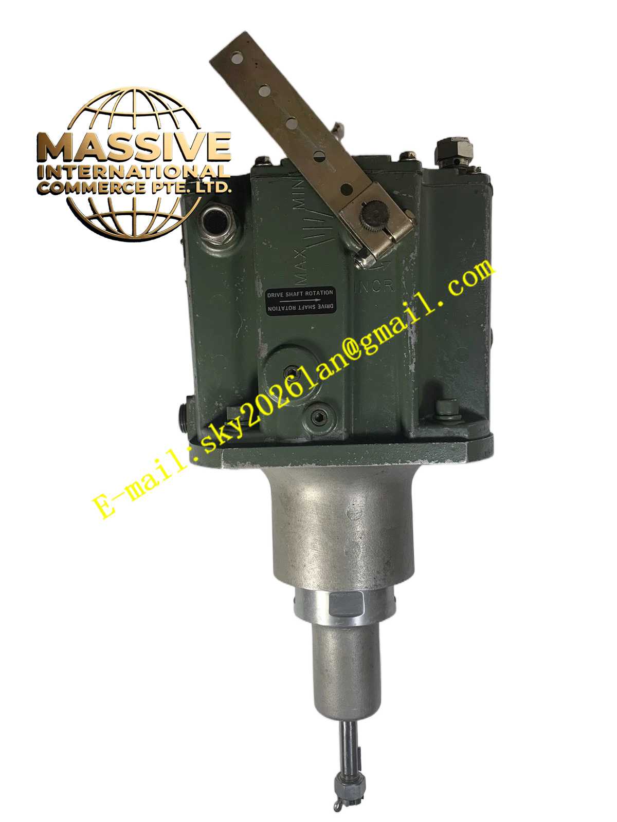
Description
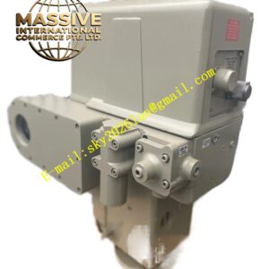
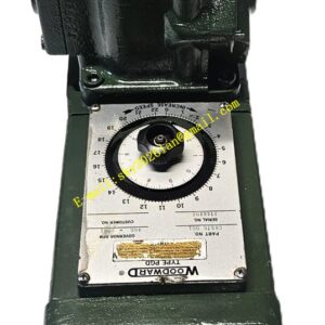
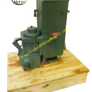
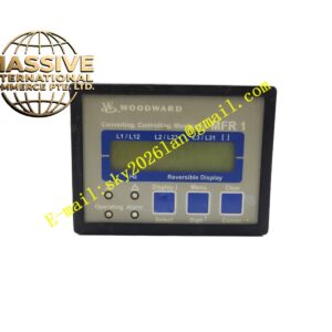
Woodward 8937-HN2
Technical Specifications
- Function: Actuator driver and signal conditioner.
- Input Compatibility: Standard analog control signals (4-20 mA, 0-10V).
- Output Drive: High-current analog output for direct actuator control.
- Feedback Input: LVDT or potentiometer feedback for closed-loop positioning.
- Power Supply: Regulated DC input with transient protection.
Functional Features
- Closed-Loop Control: Continuously compares command and feedback for exact positioning.
- Fail-Safe Operation: Drives actuator to safe position on power or signal loss.
- Signal Isolation: Galvanic isolation to prevent ground loops and noise interference.
- Diagnostics: Reports actuator faults, wiring breaks, and position errors.
Application Scenarios
Used in steam turbine valve control, engine fuel rack actuation, and industrial process control requiring precise analog positioning.
Performance Parameters
- Positioning Accuracy: Better than ±0.5% of full stroke.
- Response Time: Fast dynamic response for excellent transient performance.
- Drive Capacity: Sufficient current for high-inertia actuators.
Material Composition
High-reliability industrial electronics in a protective metal chassis with gold-plated or nickel-plated terminals for long-term conductivity.
Structural Characteristics
- Mounting: Panel-mount or DIN-rail compatible.
- Indicators: Front-panel LEDs for power, command, and fault status.
- Wiring: Clearly labeled terminal blocks for easy installation.
Working Principle
The module receives a low-level command signal and amplifies it to drive the actuator. It reads the position feedback and adjusts the output current until the actual position matches the commanded position. If a fault is detected, it initiates the fail-safe sequence.
Installation Requirements
- Install in a clean, dry environment with adequate ventilation.
- Use properly sized conductors for actuator connections.
- Ensure feedback linkage is mechanically secure and backlash-free.
Usage Precautions
- Verify fail-safe position matches mechanical safety requirements.
- Do not bypass internal protection circuits.
- Perform regular stroke tests to verify calibration and response.