Description
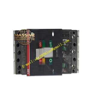
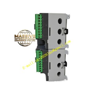
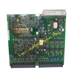
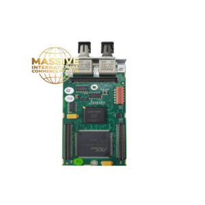
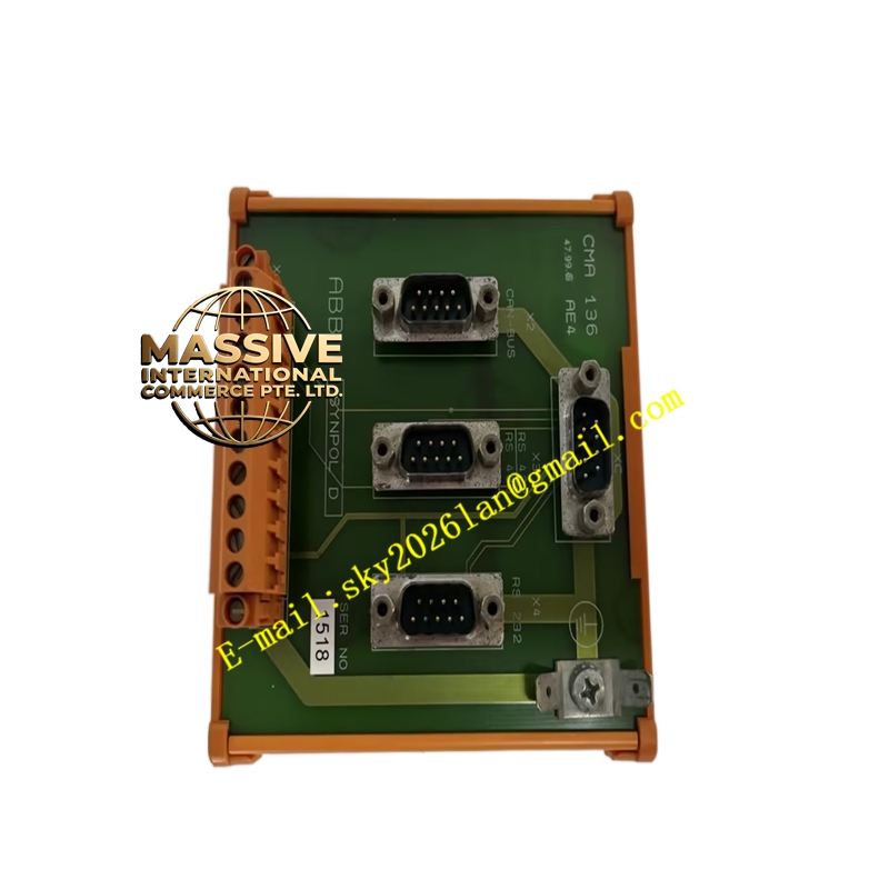
ABB CMA136 3DDE300416
Technical Specifications & Performance Parameters
- Channel Configuration: 4 groups of independent relay output channels
- Relay Contact Load Parameters:
- AC load: 5A @ 250VAC resistive load
- DC load: 10A @ 24VDC DC load
- Working Power Supply: 24VDC control power supply for internal drive circuit
- Insulation Performance: Insulation resistance ≥100MΩ between circuit board and shell; channel-to-channel isolation voltage 1000VAC
- Operating Temperature Range: -25°C ~ +70°C; storage temperature -40°C ~ +85°C
- Mechanical Life of Relay: 10 million times switching under rated load
- Protection Grade: IP20 for cabinet internal installation
- Backplane Matching: Direct plug-in with Advant DCS system standard rack backplane
Function Characteristics
- Four groups of independent relay output channels, each channel with independent isolation circuit, no mutual interference between control loads
- Receive switching control instructions from CMA126 main control module through DCS backplane bus, drive relay contact pull-in and disconnection
- Built-in surge absorption circuit for each relay channel, absorb reverse electromotive force generated by inductive loads (contactors, solenoid valves)
- Channel status LED indicator on front panel, real-time display relay pull-in/disconnection state for on-site quick inspection
- Overload protection for each output channel, automatically cut off output when load current exceeds rated value to avoid relay burnout
- Compatible with generator unit all protection interlock load equipment, realize fault trip, alarm light, auxiliary valve switch control
- Support hot-swap in DCS rack, replace terminal board without stopping generator unit DCS system
Material Composition
- Circuit board: High-temperature FR4 flame-retardant PCB, tin-lead-free anti-corrosion coating
- Relay components: Silver alloy contact industrial electromagnetic relays with long service life
- Surge absorption components: TVS transient voltage suppression diode for each channel
- Wiring terminals: Copper alloy nickel-plated screw terminals, anti-loose spring gasket
- Outer shell: Black flame-retardant ABS plastic cabinet plug-in shell
Structural Features
- Standard DCS single-width rack plug-in module, slide rail buckle fixed installation
- Front panel 4 groups of independent LED status indicators corresponding to each relay channel
- Rear panel partition layout: backplane bus contact area and field load wiring terminal area separated to avoid signal interference
- Internal independent heat dissipation channel for each relay to prevent heat accumulation of multi-channel simultaneous action
- Anti-vibration buffer pad between relay and circuit board, adapt to generator room long-term vibration environment
Working Principle
- CMA126 main control module sends switching control instructions to CMA136 through DCS rack backplane bus
- Internal drive chip receives instructions and outputs drive current to corresponding channel relay coil, pull relay contact closed
- Relay contact connects external 24VDC/220VAC load circuit to control generator protection equipment action
- Surge absorption circuit absorbs reverse electromotive force when relay coil is disconnected, protect internal drive chip
- LED indicator synchronously lights up when relay pulls in, visually feedback channel output state
Installation Requirements
- Installed in ABB Advant DCS dedicated control cabinet rack, slide rail lock fixed
- Field load wiring must be separated from DCS internal control signal wiring, separate wiring slots
- Inductive loads (contactors, solenoid valves) must not cancel built-in surge absorption circuit
- Reserve 10mm heat dissipation gap between adjacent terminal boards to avoid relay heat accumulation
- Cabinet protection ground wire connected to module shell grounding terminal
Application Scenarios
- Generator overvoltage, overcurrent protection trip contactor drive
- Power plant boiler emergency stop valve solenoid switch control
- Unit fault alarm light, sound alarm horn switch output
- Hydraulic turbine auxiliary oil pump, cooling fan interlock control
- Substation DC system fault signal remote output
Usage Precautions
- Strictly prohibit exceeding rated contact load current, long-term overload will lead to relay contact ablation
- Do not plug and unplug the module when DCS system is running to avoid generator protection misoperation
- Regularly check relay contact surface oxidation, replace the module if contact ablation occurs
- Load wiring terminal screws need to be tightened every 6 months to prevent loose contact heating
- Avoid installing near high-temperature power modules to prevent relay coil over-temperature aging