



Description
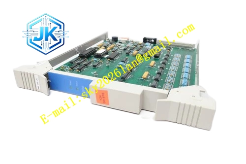
Honeywell 30754661-021
Technical Specifications Total Slot Quantity: 14 functional card slots Logic Power Distribution: 5V DC Field Power Distribution: 24V DC Bus Signal Type: UCN parallel backplane bus Bus Communication Rate: 5Mbps Power Consumption: 3.3W Operating Temperature Range: 0℃ to 65℃ Storage Temperature Range: -40℃ to 85℃ Isolation Withstand Voltage: 1500V AC Relative Humidity: 5% to 95%, non-condensing
Functional Features It provides independent power branch and signal trace for each card slot. It carries out optimized impedance matching for high-speed backplane bus signals to reduce signal reflection. It supports hot swap signal handshake for compatible pluggable modules. It integrates high-current branch fuse protection for each slot. It supports bus signal arbitration and data transmission between all inserted modules. It carries slot position identification coding for automatic module recognition by DCS system. It supports higher total rack power load compared with revision 014 version.
Application Scenarios Backplane interconnection for heavy-load TDC3000 UCN I/O racks and HPM main control racks. Replacement and upgrade of revision 014 backplane boards for legacy TPS control cabinets. Rack reconstruction and expansion project for petrochemical and chemical DCS control rooms. Stable signal routing for racks with full load of I/O processor and communication cards.
Performance Parameters Bus Signal Transmission Delay: ≤35ns per slot Power Branch Fuse Response Time: ≤1ms Slot Identification Coding Accuracy: 100% Maximum Supported Total Rack Power: 150W
Material Composition PCB Substrate: Thick copper controlled impedance FR-4 multi-layer board with upgraded power plane High-current power distribution traces and differential signal traces Precision impedance matching resistor array High-current branch fuse protection components Gold-plated slot contact spring assemblies with enhanced wear resistance Aluminum alloy fixed mounting frame with anodized anti-oxidation treatment
Structural Features Fixed large-format board structure, installed at the rear side of TDC3000 rack. Each slot corresponds to a group of gold-plated spring contact sockets for card edge finger connection. Power traces are laid on separate power plane and isolated from high-speed signal traces. Signal traces adopt differential routing layout to restrain electromagnetic interference. All contact sockets are arranged with precise positioning structure to avoid misalignment during card insertion. Heat dissipation window is reserved for high-power slot power branches.
Working Principle External rack power supply enters the board through main power terminals. The board divides input power into multiple independent branches and delivers power to each slot contact. The backplane bus signal from processor card transmits through internal signal traces to all other slots. Optimized impedance matching components eliminate signal reflection on high-speed bus. When a card is inserted, the slot coding circuit sends position identification signal to the rack processor. The bus arbitration circuit manages data transmission sequence to avoid signal conflict between multiple modules.
Installation Requirements Fix the board on the rear mounting bracket of TDC3000 rack with dedicated bolts. Connect main power cables to the power input terminals following polarity marking. Check all slot contact sockets for deformation or foreign matter before inserting functional cards. Tighten all power terminal screws to avoid excessive contact resistance and temperature rise. Verify bus communication and power supply status on the HPM diagnostic page after rack power-on.
Precautions Cut off all rack power supply before installing or removing this backplane board. Do not bend or deform the gold-plated spring contact sockets. Metal debris falling into the slot contacts causes bus short circuit and whole rack failure. Do not modify internal signal traces or power branches without engineering authorization. Overload of total rack power triggers main branch fuse blow and power loss of the whole rack.







