Description
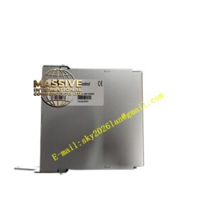
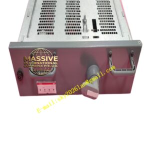
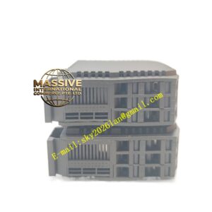
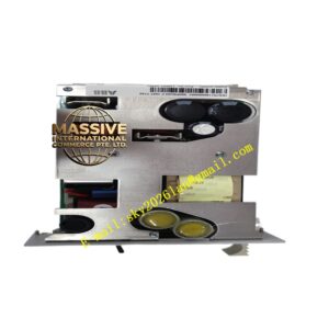
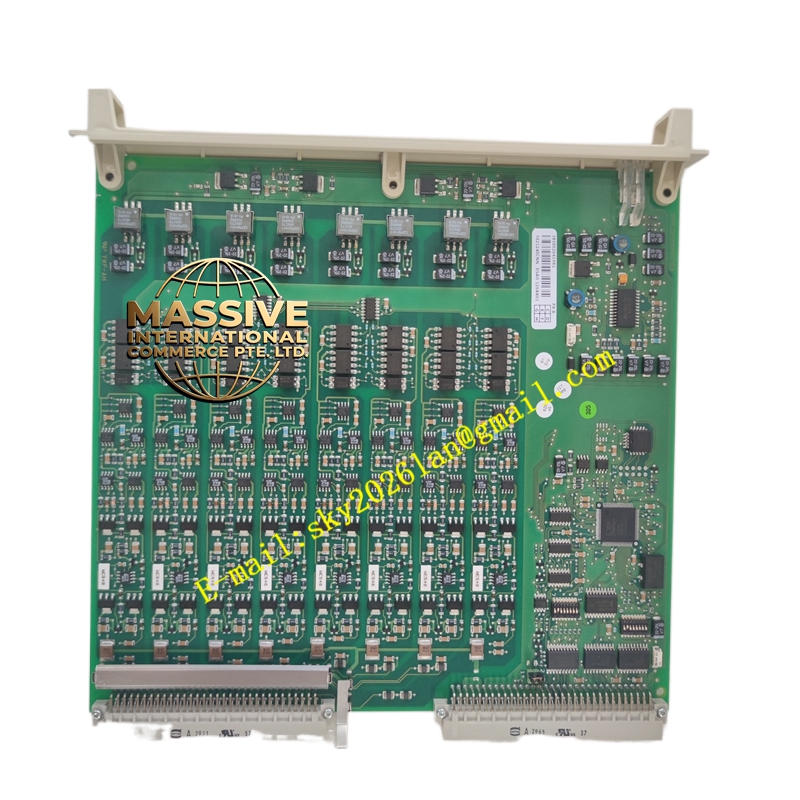
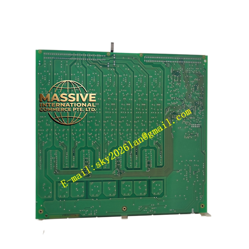
ABB DSAO120AK01 3BSE020419R1
Technical Specifications:
- Output Type: Standard industrial analog outputs (e.g., 4-20mA, 0-10V).
- Resolution: High-resolution Digital-to-Analog Converter (DAC) for smooth control.
- Isolation: Galvanic isolation between outputs and the system bus.
- Update Rate: Fast output update rate for responsive closed-loop control.
- Load Driving: Capable of driving standard industrial loop impedances.
Functional Features:
- Precise Actuation: Provides accurate and stable analog signals for precise valve positioning and motor speed control.
- Fail-Safe Modes: Configurable output behavior (hold last value, go to predefined safe state) upon communication loss or module failure.
- Loop Monitoring: Built-in diagnostics to detect open loops, short circuits, and over-range conditions.
- Ramp Function: Internal ramping capabilities to prevent sudden mechanical shocks to actuators.
Application Scenarios:
- Control valve positioning in process automation.
- Speed reference signals for VFDs and motor drives.
- Setpoint generation for PID control loops.
- Analog metering and indicator panel driving.
Performance Parameters:
- Accuracy: High-precision output with minimal linearity error.
- Stability: Low temperature drift ensures consistent performance over time.
- Response Time: Millisecond-level response to control command changes.
- Drive Capacity: Sufficient current drive for standard 4-20mA loops.
Material Composition & Structural Characteristics:
- PCB: Precision analog output circuitry with high-quality DACs and operational amplifiers.
- Enclosure: Standard industrial module housing with DIN rail mounting.
- Connectors: Secure terminal connections for field wiring.
- Indicators: Status LEDs for power, communication, and channel activity.
Working Principle:
The module receives digital control values from the controller over the backplane bus. The onboard DAC converts these digital values into precise analog voltages or currents. Signal conditioning circuits amplify and filter the output to ensure stability and accuracy. Continuous diagnostic monitoring verifies the integrity of the output loop and reports any faults to the controller.
Installation Requirements:
- Wiring: Use shielded cables for analog outputs to prevent noise-induced actuator fluctuations.
- Load Verification: Ensure the connected load impedance falls within the module’s specified operating range.
- Power: Verify adequate backplane power is available for the module.
- Configuration: Set the output type, fail-safe mode, and ramp rates in the control software.
Usage Precautions:
- Short Circuit Protection: Avoid short-circuiting output terminals; verify wiring before applying power.
- Inductive Loads: Use flyback diodes or snubbers when driving highly inductive loads.
- Calibration: Perform periodic loop checks to verify output accuracy at the field device.
- Safety: Configure appropriate fail-safe states to ensure process safety during system faults.