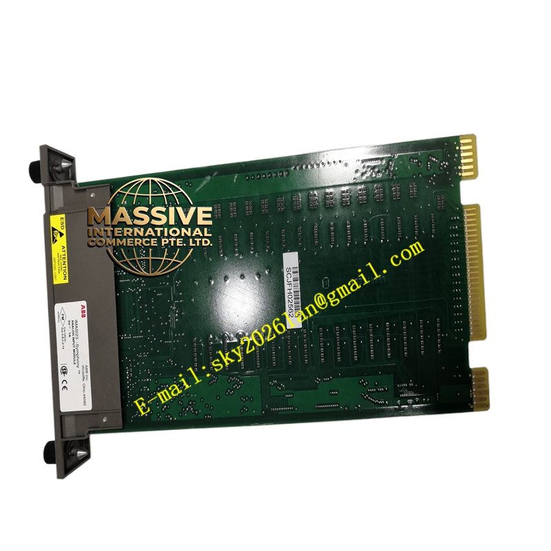
Description
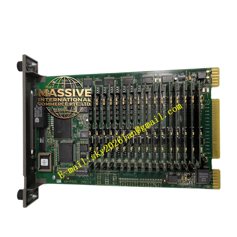
ABB IMASI23
- Technical Specifications:
- Input Channels: 16 (differential); grouped in two groups of 8 with common reference per group
- Input Types (per channel, software-selectable):
- Current: 4–20 mA, 0–20 mA (max loop resistance 500–750 Ω including cable)
- Voltage: ±10 V, 0–10 V, 0–5 V, 1–5 V
- Thermocouple: J, K, T, E, S, B, R, N (linearized; cold-junction compensation on-board or remote CJC)
- RTD: Pt100 (α=3850 ppm/°C or 3926), Ni100, Cu100 — 2-, 3-, 4-wire
- Resolution: 12-bit A/D (typical ±0.1 % FS accuracy for current/voltage); TC accuracy ±1 °C + CJC error
- Input Impedance: Current ≈250 Ω (internal shunt); Voltage >1 MΩ
- Open-Sensor Detection: Yes — reports <3.6 mA (sensor break for 4–20 mA) or out-of-range TC/RTD
- Conversion Time: ≈250 ms per full scan (all 16 channels)
- Isolation: Channel group to backplane 500 V DC working; 1500 V AC test 1 min; channel-to-channel NOT isolated within group
- Module Power: 5 V DC from backplane (typ. 300 mA); 24 V DC from backplane for excitation (typ. 50 mA)
- Indicators: Module Ready (green), Module Fault (red), C.W. Active (green)
- Operating Temp.: 0 °C to +60 °C (–20 °C storage)
- Dimensions: Single-slot INFI 90module (≈30 mm W)
- Functional Features:
- Per-channel software configuration (type, range, engineering unit scaling, alarm limits)
- Built-in linearization tables for TC/RTD; lead-wire compensation for 3-/4-wire RTD
- Digital filtering (first-order, configurable time constant) to reject 50/60 Hz noise
- Over/under-range flags and high/low alarm detection reported to controller
- Supports both internally-powered (loop-powered 2-wire Tx) and externally-powered (3-wire / 4-wire) connections
- Application Scenarios:
- Process variable acquisition — pressure (4–20 mA from DP cell), temperature (Pt100 / TC), level (radar 4–20 mA), flow (orifice DP → 4–20 mA)
- Power plant — drum level, bearing metal temperature (TC), generator winding temperature (Pt100)
- Refinery / petrochemical — reactor temperature (TC Type K/S), column pressure (4–20 mA)
- Retrofit of legacy INFI 90 plants — direct plug-in replacement for older I/AIM analog input modules
- Material & Structure:
- Housing: Flame-retardant ABS/PC with transparent status window
- PCB: Industrial FR4, conformal-coated (G3 per ISA-S71.04on process-grade versions)
- Edge Connector: 30-pin gold-plated for backplane engagement
- Keying: Physical key on module bottom engages coded slot in IEMMU21
- Working Principle:
Analog field signals pass through input filtering and are multiplexed to a precision A/D converter. For TC inputs, the module reads the on-board or remote CJC sensor temperature and applies linearization + CJC correction. For RTD, an excitation current (typically 0.5–1 mA) is sourced; voltage is measured and converted to resistance → temperature using Callendar–Van Dusen equation. Digitized values are placed in the module’s C.W. data table and read by the controller each scan cycle. Open-circuit or over-range conditions set quality flags.
- Installation Requirements:
- Insert IMASI23 into any available I/O slot (slots 2–10 typically; slot 1 reserved for controller/comm module) of IEMMU21 with key aligned
- Wire field signals to termination block / marshalling terminal corresponding to the I/O rack (INFI 90 uses separate TB or TA (Termination Assembly) — e.g., TA567 for analog inputs)
- For 4–20 mA 2-wire Tx: connect + from Tx to Ix(+), – from Tx to Ix(–)/common; ensure loop power (24 V DC) is supplied either by external PSU or by TA567 loop-power option
- For RTD 3-wire: connect two leads to Ix(+) and one to Ix(–) per diagram; 4-wire: two sense, two excite
- For TC: use compensating/extension wire of correct type; connect +/– per diagram; avoid mixing TC types on same group if CJC is shared
- In Control Builder / INFI 90 Configurator, define module type = IMASI23, assign starting block address, configure each channel’s signal type & range
- Precautions:
- Verify loop power polarity for 2-wire 4–20 mA transmitters — reversed polarity gives 0 mA / erroneous reading
- Do NOT apply >30 V DC to analog input terminals — may damage A/D front end
- For TC: shield should be grounded at one end only (typically cold junction / cabinet end) to avoid ground loops; keep TC wires separated from AC power / VFD cables
- For RTD: 3-wire connection requires lead resistance balance for best accuracy — use same gauge/length for both “excite” leads
- Confirm CJC sensor is not obstructed by warm air currents — affects TC accuracy