



Description
Honeywell 51308012-100
Technical Specifications Channel Quantity: 8 independent pulse channels Supported Input Signal: 24V active pulse, passive dry contact pulse Maximum Input Frequency: 10kHz Independent 32-bit hardware counter for each channel Power Supply: 24V DC Power Consumption: 6.1W Operating Temperature Range: 0℃ to 60℃ Storage Temperature Range: -40℃ to 85℃ Isolation Withstand Voltage: 1500V AC Relative Humidity: 5% to 95%, non-condensing
Functional Features Each channel owns independent hardware counter and does not occupy controller computing resources. Input type can be switched by software configuration. It supports pulse debounce filtering to eliminate false pulses from mechanical contact bounce. It provides instantaneous frequency conversion and total flow accumulation. Accumulation value is retained by on-board capacitor for short power interruption. It supports hot swap. Fault status including no signal and open circuit is uploaded to DCS alarm system.
Application Scenarios Pulse flow acquisition and totalization for turbine meters and vortex meters. Speed signal collection for fans, pumps and compressors with incremental encoders. Pulse signal input from belt scales and volumetric metering devices. Replacement and expansion of pulse measurement points in UCN I/O racks.
Performance Parameters Frequency Measurement Accuracy: ±0.05% Minimum Pulse Width: 50μs Debounce Time: Adjustable from 0.1ms to 10ms Counter Overflow Threshold: 2³²
Material Composition PCB Substrate: FR-4 flame-retardant multi-layer board High-speed edge capture chips 32-bit counting logic units Photoelectric isolation chips for each channel group Gold-plated detachable terminal blocks Anti-static coated front panel
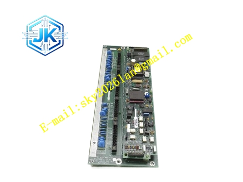
Structural Features Standard European pluggable card suitable for UCN I/O rack slots. Front panel includes run indicator, fault indicator and 8 channel pulse status indicators. Front detachable terminal block marked with pulse positive, negative and common terminals. Gold-plated edge fingers connect to the UCN rack backplane bus. High-speed pulse signal area adopts independent shielding to reduce digital noise interference.
Working Principle Pulse signals enter the module terminals. Photoelectric isolators identify rising or falling edges of pulses and trigger hardware counters to increment. The on-board MCU converts pulse frequency into instantaneous flow according to configured meter factor and accumulates total flow. Valid data is packaged and transmitted to the HPM controller via UCN bus. The module continuously monitors long-term signal loss and circuit open circuit conditions and triggers alarms.
Installation Requirements Insert the module vertically into the rack slot and tighten fixing screws. Use shielded twisted pair cables for pulse wiring. Shield grounding only at cabinet side. Pulse cables must be separated from inverter output cables and high-power cables. Configure meter factor and edge trigger mode in Control Builder before commissioning. Verify pulse amplitude for active pulse loops to avoid overvoltage input.
Precautions Long-distance pulse transmission adopts differential pulse instruments to reduce interference. Increase debounce time when mechanical contact meters produce unstable pulse signals. Total accumulation value will clear after long-time power loss. This module cannot receive 4-20mA analog signals.







