



Description
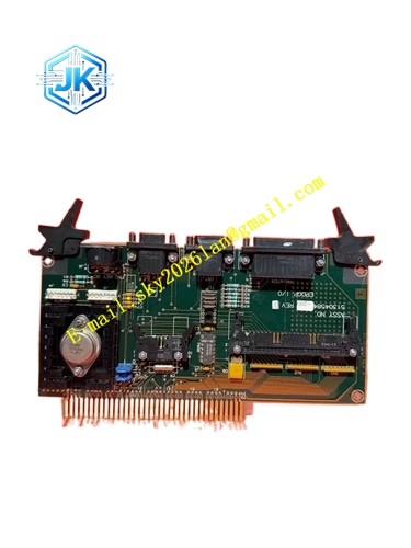
Honeywell 51304584-200
Technical Specifications Channel Quantity: 8 channels, grouped isolation with 4 channels per group Output Signal: 4-20mA DAC Resolution: 16-bit Power Supply: 24V DC Power Consumption: 7.4W Operating Temperature Range: 0℃ to 60℃ Storage Temperature Range: -40℃ to 85℃ Isolation Withstand Voltage: 1500V AC Relative Humidity: 5% to 95%, non-condensing
Functional Features Grouped electrical isolation prevents ground loop crosstalk between output channels. Each channel supports independent fail-safe mode configuration including hold, zero and full scale. It continuously detects output loop open circuit, short circuit and overload conditions and uploads fault alarms. It has built-in current limiting protection to protect DAC chips under short-circuit conditions. It supports hot swap. Output range and filter parameters can be downloaded remotely via Control Builder.
Application Scenarios PID regulation output for control valves in reactors, distillation columns and heat exchangers. Control signal output for I/P transducers and electric regulating actuators. Replacement and expansion of analog output points in legacy UCN I/O racks. Regulating loop control for boiler auxiliary systems and utility units.
Performance Parameters Output Accuracy: ±0.12% Full Scale Settling Time: ≤80ms Common Mode Rejection Ratio: ≥102dB Output Ripple: ≤12μA
Material Composition PCB Substrate: High-TG FR-4 multi-layer glass fiber board 16-bit DAC digital-to-analog conversion chips Grouped photoelectric isolation components Low-noise operational amplifiers Gold-plated wiring terminals Cold-rolled steel front panel with electrostatic spray coating
Structural Features Standard European pluggable card matching UCN I/O rack slots. Front panel equipped with run indicator, fault indicator and group status indicators. Detachable terminal block with channel number and polarity marking. Gold-plated edge fingers connect to the UCN rack backplane bus. Analog output area is shielded independently from digital logic circuits.
Working Principle The module receives digital setpoint values from the HPM controller through the UCN bus. The on-board MCU distributes the digital values to corresponding DAC channels. The DAC converts digital signals into continuous 4-20mA current for field control loops. The module feeds back actual loop current readings, identifies abnormal circuit conditions and sends fault information to the controller.
Installation Requirements Insert the module vertically into the rack slot and tighten fixing screws. Use shielded twisted pair cables for output wiring. Shield layer is grounded only at cabinet side. Keep output cables away from high-power cables and inverter output cables. Download configuration after wiring and verify the consistency between valve feedback and DCS output. Maintain loop load resistance within the rated range to avoid signal distortion.
Precautions Do not connect high voltage to output terminals. High voltage surge will burn isolation and DAC circuits. This module does not support HART signal superimposition. Condensation and moisture on terminal blocks will cause signal drift and short circuit. Verify fail-safe configuration after each configuration download.







