



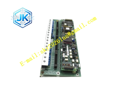
Description
Honeywell 51308014-100
Technical Specifications Channel Quantity: 8 isolated RTD channels Supported Sensor: Pt100, Pt1000 Wiring Mode: Two-wire, three-wire, four-wire configurable ADC Resolution: 16-bit Power Supply: 24V DC Power Consumption: 7.3W Operating Temperature Range: 0℃ to 60℃ Storage Temperature Range: -40℃ to 85℃ Isolation Withstand Voltage: 1500V AC Relative Humidity: 5% to 95%, non-condensing
Functional Features Built-in constant current excitation circuit automatically compensates lead resistance for three-wire and four-wire wiring. It integrates hardware low-pass filtering to suppress 50Hz industrial frequency interference. It detects sensor open circuit, short circuit and over-range conditions and uploads alarms. Sensor type, wiring mode and sampling period can be configured remotely. It supports hot swap. Single channel fault does not affect temperature acquisition of other channels.
Application Scenarios Wall temperature and medium temperature measurement of heating furnaces and cracking furnaces. Multi-point temperature monitoring of heat exchanger clusters and air separation units. Bearing temperature measurement of rotating equipment including pumps and fans. Replacement and expansion of RTD temperature points in UCN I/O racks.
Performance Parameters Measurement Accuracy: ±0.1℃ for Pt100 four-wire mode Sampling Cycle: Adjustable from 100ms to 2s Common Mode Rejection Ratio: ≥110dB
Material Composition PCB Substrate: Low-noise high-TG FR-4 multi-layer board Constant current excitation chips Precision cold-end compensation RTD element Analog multiplexer array Photoelectric isolation components Gold-plated detachable terminal blocks Anti-static coated front panel
Structural Features Standard European pluggable card matching UCN I/O rack slots. Front panel equipped with run indicator, fault indicator and group status indicators. Detachable terminal block with RTD lead marking. Gold-plated edge fingers connect to the UCN rack backplane bus. Weak temperature signal area adopts large-area copper shielding and separates from digital circuits.
Working Principle The constant current source inside the module injects tiny stable current into the connected RTD sensor. The module measures voltage drop across the RTD and calculates resistance value. The resistance value is converted to temperature reading according to standard RTD lookup table. Lead resistance is deducted automatically in three-wire and four-wire modes. Temperature data is packaged and uploaded to the HPM controller via UCN bus. Sensor fault conditions are identified and marked for alarm.
Installation Requirements Adopt dedicated RTD shielded compensation cables for field wiring. Shield grounding only at cabinet side. Select four-wire wiring mode for highest measurement precision. Separate temperature cables from inverter and high-power cables. Configure sensor type and wiring mode in Control Builder before commissioning.
Precautions Two-wire wiring generates obvious measurement error for long-distance sensors. Moisture and dust accumulation on terminal blocks cause signal drift. This module only supports RTD resistance sensors and cannot directly receive thermocouple millivolt signals.







