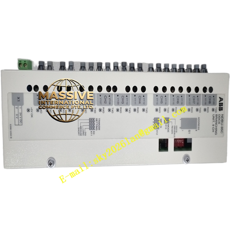
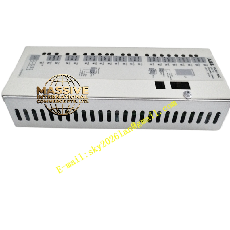
Description
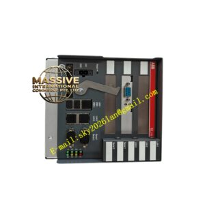
ABB NDBU-95 (64008366)
- Technical Specifications:
- Function: DDCS bus repeater / distributor — receives fiber-optic DDCS from master, regenerates & distributes to up to 5–7 slave nodes (per ABB DDCS fan-out rules)
- Fiber Ports: Typically 1 × DDCS IN (from master), 3–5 × DDCS OUT (to slave inverters or next NDBU-95); ST-type connectors (820 nm or 1300 nm per DDCS version)
- Max Fiber Length (per segment): 50 m multimode (830 nm) typical for DDCS; 300 m (1300 nm) on some versions — check drive manual
- Power: 24 V DC from drive internal supply (or from AINT board header)
- Indicators: Power LED, Link Active LED per port
- Operating Temp.: –20 °C to +60 °C
- Dimensions: ≈100 × 70 mm PCB; DIN-clip or header-mount
- Conformal Coating: Present on “-C” version (NDBU-95C) per G3 ISA-S71.04
- Functional Features:
- Regenerates DDCS telegrams — allows longer multi-drop chains than direct fiber from RDCU
- Provides electrical isolation between DDCS segments (via fiber)
- Used in common-DC-link multi-inverter setups (e.g., paper machine sectional drive — one rectifier feeding 6 inverter modules, each with its own ACS800 + NDBU-95 tapped off DDCS bus)
- Application Scenarios:
- Sectional drive paper machine — master rectifier + DC link, 4–12 inverter drives each receiving DDCS reference via NDBU-95 distribution
- Wind tunnel / dynamometer — master speed reference fanned out to multiple load absorbers
- Retrofit / expansion of existing ABB multi-drive system — add NDBU-95 to increase DDCS node count
- Material & Structure / Working Principle / Installation / Precautions:
- Mount NDBU-95 inside drive cabinet; connect IN fiber from master (RDCU/AINT DDCS TX); connect OUT fibers to each slave drive’s DDCS RX port
- Verify fiber polarity (Tx→Rx; some DDCS uses simplex — one fiber per direction; others use duplex — follow ACS800 fiber diagram)
- In drive system, no configuration needed — DDCS is transparent; each slave drive is addressed via DIP switches on its AINT/NDCU board
- Precautions:
- Do NOT bend fiber beyond minimum bend radius (≈30 mm for 62.5/125 µm multimode)
- Clean fiber end-faces before mating — contamination causes high attenuation / intermittent DDCS loss
- Do NOT look into powered fiber — invisible IR (820/1300 nm) — though low power, good practice to avoid direct viewing
- In multi-drop, ensure total number of nodes and fiber length stay within DDCS spec — exceeding causes timing violations