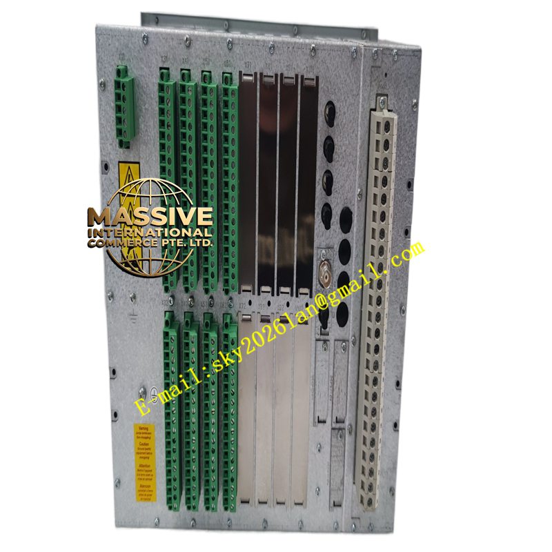
Description
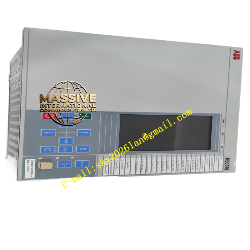
ABB REC670 1MRK002814-AC
- Technical Specifications (typical REC670 line IED):
- Inputs:
- Current: 3 × phase CT (1 A / 5 A selectable), 1 × neutral CT (I0)
- Voltage: 3 × phase VT (100 V / 110 V / 120 V L-L), 1 × Vn (V0 if 4-wire)
- Binary Inputs: 8–16 (wet / dry contact, 24 V DC / 110 V DC / 220 V DC depending on option)
- Outputs: 8–16 × programmable relay contacts (SPDT / SPST — trip, close, alarm, healthy, BF)
- Display: Large graphical LCD (640×480) + keypad — local setting, event review, disturbance waveform
- Time Sync: IRIG-B, SNTP, PTP (IEEE 1588 v2)
- Disturbance Recorder: ≥100 COMTRADE files; pre-fault / post-fault trigger; sampling up to 4 kHz
- Power Supply: 110/220 V DC or 230 V AC (dual redundant supply option)
- Operating Temp.: –20 °C to +55 °C (storage –40 °C to +70 °C)
- Case: 4U half-rack (19″) or 4U full-rack; DIN-rail / panel mount variants in 670 compact versions
- Certifications: IEC 60255, IEC 61850-3/5-7, KEMA type-tested, IEEE C37.90, CE, UL
- Settings: Via front panel, PCM600 (ABB protection engineering tool), or SCL (SCD file via IEC 61850)
- Inputs:
- Functional Features:
- Multi-zone distance with communications-assisted tripping (POTT / DCB / DCUB schemes)
- Optional 2-end / multi-end current differential (87L) with fiber or IEC 61850-9-2sampled values
- Adaptive reclosing (check synchro before reclose)
- Breaker failure protection & breaker condition monitoring (operations counter, trip coil minimum current)
- Integrated disturbance & sequence-of-events recording for post-fault analysis
- Cyber-security: role-based passwords, audit trail, IEC 62351(on newer FW)
- Application Scenarios:
- 132 kV / 220 kV / 400 kV transmission line main protection (Zone 1 = 80–90 % line; Zone 2 = line + 20 % remote; Zone 3 = backup)
- Parallel line protection with intertrip via fiber (POTT scheme)
- Substation integration — REC670 as IEC 61850IED reporting to IEC 61850-8-1MMS station bus + GOOSE for inter-IED tripping
- Retrofit of older electromechanical / static distance relays (e.g., BBC / ABB RAZOA, REL511)
- Material & Structure:
- Housing: Aluminum / steel 4U case, gray (RAL 7035) or black; front Lexan window with keypad overlay
- Terminals: Plug-in screw / spring-cage CT/VT terminals (rear) + binary I/O plug-in strips
- Cooling: Natural convection (no fan in typical 670)
- Battery: Internal supercap or coin cell for RTC backup (≥10 years typical)
- Working Principle:
The IED continuously samples line currents & voltages via CT/VT secondaries (or via merging unit SV stream in process bus config). Distance algorithm computes apparent impedance (R,X) seen by relay → compares to zone characteristics (quadrilateral mho). If impedance falls within Zone 1 polygon → instantaneous trip; Zone 2 → delayed trip (coordinate with remote Zone 1); Zone 3 → remote backup. Directional element ensures only faults in protected direction cause trip. On receive of intertrip signal (POTT/DCB) → accelerate Zone 2 to instantaneous. Line Diff (if enabled) compares local & remote currents (vector sum → Ires / Idiff) → trips if Idiff > slope × Ires + pickup.
- Installation Requirements:
- Mount in 19″ panel or on DIN rail (compact version); ensure ventilation
- Wire CT secondaries (observe polarity: Ia→A, Ib→B, Ic→C, In→N; polarity critical for directional & diff) — CT secondaries MUST be shorted until REC670 connected & verified
- Wire VT secondaries (Va,Vb,Vc,Vn) — fused per local code (typically 0.5 A gG/gR HRC fuse)
- Connect 110/220 V DC station battery / PSU to PSU terminals; connect PE
- Connect binary inputs (breaker aux contact “52a”, external intertrip, protection disable) & outputs (trip coil circuit via auxiliary tripping relay / direct if rating permits — check make/break capacity)
- Connect IRIG-B / NTP for time sync; connect Ethernet (IEC 61850 MMS / GOOSE) or serial (60870-5-103) to substation LAN
- In PCM600: create REC670 project → import SCD or manually set line parameters (CT/VT ratio, zone reach %, angles, directional char, reclosing timers) → download → perform secondary injection test (6-point polar plot + diff test) → authorize to service
- Precautions:
- CT Secondaries: NEVER open-circuit energized CT — lethal HV & CT damage. Always short CT secondaries before disconnecting REC670. Verify CT circuit continuity with ohm-meter (power off) before energizing VT/CT primaries.
- VT Fuses: Use correctly rated HRC fuses; verify polarity — reversed VT → distance characteristic rotates → mal-operation.
- Zone Settings: Coordinate Zone 2 reach with remote end’s Zone 1 + C’b line (typically Zone 2 = 120 % of line impedance); Zone 3 = (Line Z + Remote Step-up Z) × 1.2 — validate with protection engineer.
- Test Before Close: After param download, do secondary injection test — verify zone timing & directional element — BEFORE closing breaker onto line.
- For Line Diff: verify fiber link BER <1E-9; check time sync quality (both ends must be time-synced for sample-aligned diff — typically IRIG-Bor PTP); set slope & unrestrained diff pickup per protection study.
- Change Control: Any setting change must be documented, authorized, and version-controlled — relay settings are legal documents in many jurisdictions.