Description
Basler Electric BE3-25A
Technical Specifications Microprocessor-based protection design; supports configurable overcurrent, overvoltage, undervoltage and phase loss protection functions; rated control power 120V AC or 240V AC; 5A secondary current input for current transformer circuits; operating ambient temperature range -40°C to +85°C; front-panel digital display; programmable trip delay settings; relay output contacts rated for 250V AC, 5A resistive load; IP40 front panel protection rating.
Functional Features Continuously sample current and voltage signals from instrument transformers in power circuits. Compare measured electrical values against user-configured protection thresholds. Activate trip output contacts to trigger circuit breaker opening when fault conditions are satisfied. Record fault event data including fault type, magnitude and timestamp in non-volatile memory. Provide local LED status indication and remote communication interface for SCADA system connection. Support protection setting adjustment through front keypad or software. Execute built-in self-test routines during power-up and normal operation to detect internal hardware faults.
Application Scenarios Generator set protection, industrial distribution feeder protection, transformer secondary circuit monitoring, backup protection for motor control centers, power co-generation system fault supervision.
Performance Parameters High measurement precision for AC electrical quantities; fast fault detection response; stable operation under power system harmonic distortion; reliable event data retention after auxiliary power loss; wide threshold adjustment range for diverse protection schemes.
Material Composition Main printed circuit board uses FR-4 flame-retardant multilayer substrate; signal sampling and processing chips are industrial microprocessors and precision operational amplifiers; isolation transformers and optocouplers separate high-power instrument transformer circuits from low-voltage logic circuits; front panel is flame-retardant ABS plastic; terminal blocks adopt nickel-plated copper alloy contacts; internal relay contact material is silver cadmium oxide alloy.
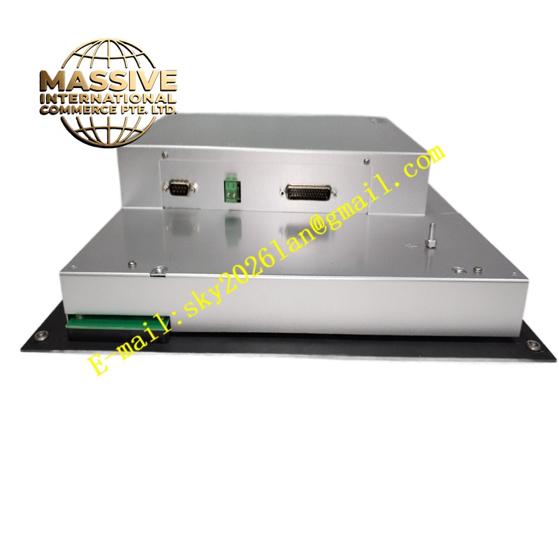
Structural Characteristics Standard panel-mount rectangular enclosure. Front panel integrates digital display, function keypad and status LED indicators. Rear side features screw-type terminal blocks for CT, VT, auxiliary power and trip wiring. Internal layout separates low-voltage control logic area and instrument signal input area. The housing includes mounting flanges for panel cutout installation.
Working Principle Current and voltage signals from current transformers and voltage transformers pass through isolation and signal conditioning circuits. The onboard microprocessor converts conditioned analog signals into digital values and calculates power system electrical parameters. When measured parameters cross preset protection thresholds with delay conditions satisfied, the unit energizes trip relay contacts to isolate the faulted circuit. All fault records store in internal memory for post-fault analysis.
Installation Requirements Prepare a standard rectangular cutout on the electrical control panel. Insert the relay unit into the cutout and fasten the mounting flanges to the panel. Wire current transformer secondary circuits, voltage transformer circuits and auxiliary power supply to rear terminals following official wiring diagrams. Configure protection thresholds, delay timers and communication parameters through front keypad. Perform secondary injection test to verify protection pickup and trip operation after commissioning.
Precautions for Use Short-circuit current transformer terminals before disconnecting relay CT wiring. Do not exceed the rated voltage and current limits of input terminals. Maintain panel sealing integrity to prevent dust and moisture ingress. Back up protection setting files before firmware upgrade or unit replacement.