Description
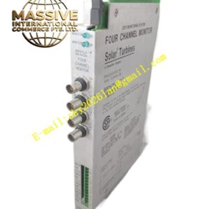
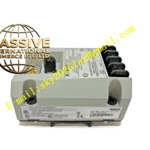
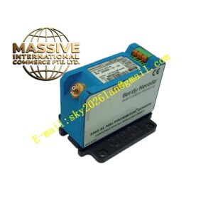
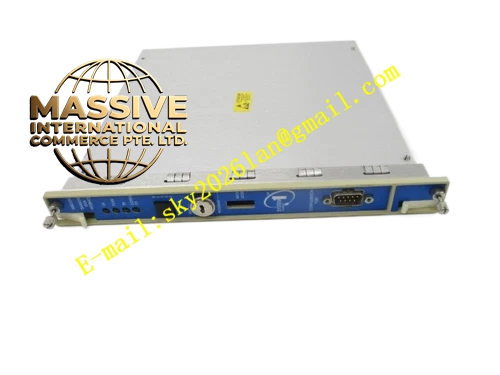
Bently 126648‑01
Technical Specifications:
- Form Factor: Full‑height 3500 rack slot module
- Input Channel: 2 independent isolated Keyphasor input channels
- Output Channel: 2 isolated buffered Keyphasor output channels
- Supported Input Signal Type: Magnetic pickup sine‑wave signal, proximity probe pulse signal, square‑wave pulse signal
- Input Frequency Range: 0.01 Hz to 20 kHz
- Input Voltage Threshold: Adjustable trigger level for zero‑crossing detection
- Galvanic Isolation: 2500 Vrms isolation between field side and rack back‑plane side
- Termination Mode: External field‑wiring termination via front removable terminal block
- Hot‑Swap Support: Full hot‑swap capability under rack powered condition
- Operating Temperature: ‑30 °C ~ +65 °C
- Storage Temperature: ‑40 °C ~ +85 °C
- Relative Humidity: 5%‑95% RH non‑condensing
- Power Consumption: Max 11 W
- Weight: 1.0 kg
- Communication: Data exchange through 3500 rack back‑plane to gateway and monitor modules
- Self‑Diagnosis: Hardware fault detection, signal amplitude abnormality monitoring Functional Features:
- Dual‑channel independent galvanic isolation structure, completely breaks ground‑loop noise induced by multi‑system signal tapping.
- Accept both passive magnetic‑pickup sine‑wave signals and active square‑wave pulse signals from field transducers.
- Buffered isolated output channels copy Keyphasor reference signal and distribute to external analyzers, DCS and third‑party monitoring instruments without signal attenuation.
- Adjustable zero‑crossing trigger threshold adapts variable‑amplitude pulse signals from low‑speed to high‑speed rotating shafts.
- Hot‑swap design allows module replacement without rack power shutdown, keeps other monitoring channels running continuously.
- Front‑panel multi‑color LED indicators display channel signal status, trigger event and module hardware fault for rapid on‑site troubleshooting.
- All functional parameters configured by 3500 configuration software, no manual hardware jumper modification required.
- Provides high‑precision timing reference for 1X,2X amplitude‑phase calculation, rotor orbit generation and rotor dynamic fault diagnosis. Application Scenarios: Phase reference signal acquisition for steam turbines, gas turbines, centrifugal compressors and large generator sets; multi‑system shared Keyphasor signal distribution; machinery fault‑diagnosis system trigger‑source input; retrofitting isolation upgrade for existing 3500 rack systems. Performance Parameters: Phase measurement accuracy ≤0.1°; pulse jitter less than 1 µs; isolation‑circuit leakage current extremely low; strong common‑mode noise rejection capability; high MTBF for long‑term continuous industrial operation. Material Composition: Multi‑layer analog‑digital mixed‑signal printed circuit board; high‑voltage isolation transformers; industrial‑grade high‑speed comparator chips; metal front panel with LED windows; reinforced plastic module frame; gold‑plated back‑plane edge connector; removable green screw terminal block assembly. Structural Characteristics: Standard full‑height 3500 rack module dimension; front‑mounted removable external‑termination terminal block; metal front‑panel with status indicator LEDs; rear gold‑plated edge connector mates with rack back‑plane; front‑panel locking screws for mechanical fastening. Working Principle: Field‑input Keyphasor pulse signal enters module through front‑side terminal block. Isolation transformer provides galvanic separation between field circuit and rack internal circuit. High‑speed comparator circuit detects zero‑crossing points of input waveform and converts analog waveform into digital trigger pulses. Onboard FPGA captures precise timestamp for each trigger event. Digital timing data transmits to other monitor modules via rack back‑plane. Buffered output circuit regenerates isolated copy of Keyphasor pulse signal for external equipment. Onboard self‑diagnosis circuit continuously monitors input‑signal amplitude and module hardware health. Installation Requirements:
- Insert module into designated full‑height slot of 3500 rack, push fully seated, tighten front‑panel locking screws.
- Route magnetic‑pickup or proximity‑probe Keyphasor wiring to front removable terminal block strictly following official wiring schematic.
- Separate Keyphasor signal cables away from high‑current power and inverter cables to reduce electromagnetic interference.
- Complete trigger‑threshold setting and channel configuration inside 3500 configuration software, download parameter set to rack hardware.
- Verify LED trigger indicator flickers synchronously with shaft rotation after power‑on commissioning. Usage Notes:
- When performing hot‑swap replacement, avoid direct contact with rear gold‑plated edge connector contacts while rack remains powered.
- Do not apply over‑voltage onto Keyphasor input terminals; over‑voltage will damage internal isolation and comparator circuits.
- Keep terminal‑block screws tightened during unit overhaul; loose wiring will cause missing trigger pulses and phase‑calculation failure.
- Module housing cannot be disassembled. No component‑level on‑site repair, replace complete module upon hardware failure.
- Confirm trigger threshold matches actual Keyphasor signal amplitude; improper threshold will produce missing or false trigger events.