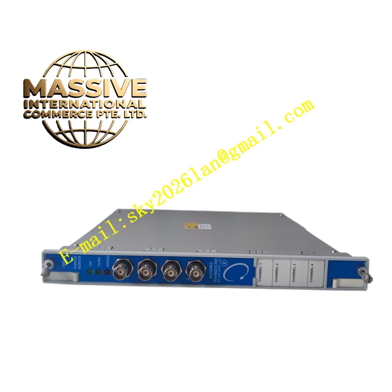
Description
Bently 1900/65A‑01‑01‑03‑00
- Technical Specifications
- Physical mounting: Standard 35 mm DIN‑rail mount
- Analogue input channels: 4 multi‑functional dynamic input channels; 4 temperature input channels
- Dynamic sensor compatibility: 2‑wire velocity transducer, IEPE accelerometer, eddy‑current proximity probe input
- Temperature input support: Type K, J, E, T thermocouples; 2‑wire /3‑wire Pt100 RTD sensors
- Relay outputs: 6 programmable electromechanical relays; each relay configurable Alert / Danger / OK status
- Relay contact rating: 5 A @250 VAC resistive load
- Analogue recorder output: 4 channels isolated 4‑20 mA
- Buffered sensor output: BNC buffered raw signal for portable diagnostic instrument connection
- Communication interface: RS‑485 Modbus RTU, optional RS‑232
- Power supply requirement: 24 VDC nominal, allowable range 18‑30 VDC
- Operating temperature: ‑30 °C ~ +65 °C
- Storage temperature: ‑40 °C ~ +85 °C
- Enclosure protection: IP20 for cabinet‑only installation
- Certification: ATEX, IECEx, CSA certified for hazardous location installation
- Functional Features: All channel functions are software configurable via dedicated PC configuration tool; no hardware modification required to swap sensor types. Independent Alert and Danger threshold values for every measurement channel. Relay action logic, time delay and voting settings fully adjustable. Built‑in event log stores timestamped alarm, danger, fault and power‑cycle records. Buffered raw sensor output enables on‑site spectrum analysis without disconnecting field sensors. Hardware fault detection covers sensor open‑circuit, short‑circuit and power supply abnormality. Isolated analogue outputs reduce ground‑loop noise risk. Modbus data makes vibration and temperature trends available for plant central control system. Supports both normally open and normally closed relay contact mode for interlock circuit design flexibility.
- Application Scenarios: Condition protection for pumps, fans, blowers, small‑frame compressors, gearboxes, exhausters and auxiliary turbo‑equipment. Widely used inside power‑plant auxiliary systems, refinery auxiliary units, water‑treatment plants, paper mills and general heavy‑industry facilities. Ideal for non‑critical rotating assets where users desire local protection interlock plus remote data transmission to DCS/SCADA. Deployed in classified hazardous cabinets within petrochemical sites.
- Performance Parameters: Dynamic signal sampling rate high enough for machinery vibration frequency analysis up to 10 kHz. Each channel independent threshold with configurable alarm time delay to avoid false triggering caused by transient spikes. Event log can hold hundreds of time‑stamped historical events. Sensor fault detection response time less than 200 ms. Analogue 4‑20 mA output accuracy ±0.15 % full scale. Galvanic isolation between field input and communication ports suppress ground loop interference.
- Material Composition: Main housing made of flame‑retardant industrial plastic with metal heat‑dissipation framework inside. Detachable screw terminal blocks use high‑conductivity copper alloy. Multi‑layer industrial grade printed circuit board with surge‑protection components for field‑side transients.
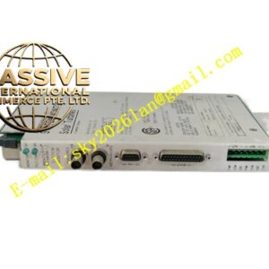
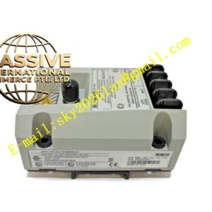
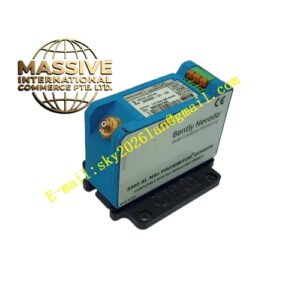
- Structural Characteristics: Rectangular slim DIN‑rail housing. Front panel equipped with status LED indicators for power, channel alarm and module fault. Front access configuration port for PC tool connection. Multiple detachable screw terminal blocks organised separately for sensor inputs, relay outputs, analogue signals and DC power. Ventilation slots distributed along upper and lower housing edges for passive heat dissipation. No internal fan, fully passive cooling.
- Working Principle: Field sensors feed analogue signals into monitor input terminals. Internal circuit performs signal conditioning, anti‑aliasing filtering and analogue‑to‑digital conversion. Firmware executes continuous real‑time calculation of vibration magnitude, temperature value. Measured values compare with user‑configured Alert and Danger set‑points. When measured value exceeds threshold for longer than programmed delay period, corresponding relay activates. Process values are converted to 4‑20 mA analogue and digital Modbus registers, sent outward to upper‑level control systems. Built‑in diagnostics detect broken wiring or sensor failure and flag fault status.
- Installation Requirements: Install inside closed electrical control cabinet, ambient must stay within rated temperature range. Maintain minimum clearance above and below module for airflow. Route low‑level sensor cables separate from high‑voltage power wiring to minimise electromagnetic interference. Use shielded twisted‑pair cables for all transducer inputs. 24 VDC power source must have industrial grade ripple filtering. Complete full parameter configuration from PC software before connecting field sensors. Verify relay contact load rating matches interlock circuit requirement. Cabinet earth connection must be reliable.
- Usage Notes: Module is IP20 rated; never deploy outside cabinet. Do not exceed relay contact electrical rating. Always confirm software channel configuration matches physical connected sensor type; misconfiguration creates wrong readings. Keep Modbus communication cable shield connected to single‑point earth. Periodically download event log during equipment turnaround to trace historical abnormal events. Do not perform hot‑swap wiring while module remains powered.