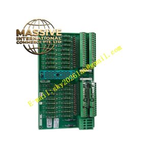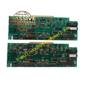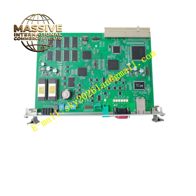
Description
CEGELEC CSR70
Technical Specifications Power supply range 24 V DC to 250 V DC or 85 V AC to 265 V AC; sampling rate for current and voltage signals supports 50 Hz and 60 Hz networks; configurable protection functions include overcurrent, earth fault, overload, undervoltage, overvoltage, negative sequence protection; multiple programmable logic inputs and relay trip outputs; local LCD display and keypad for parameter viewing and setting; serial communication interface supporting Modbus RTU; operating ambient temperature -10 ℃ to +60 ℃; DIN rail or panel mounting options.
Functional Features Multi-stage overcurrent protection with definite time and inverse time characteristic curves; earth fault protection for insulated or earthed distribution systems; thermal overload protection with memory of accumulated thermal energy; fault event recording and fault value storage; programmable logic scheme for interlock and auto-reclose sequences; password protection for parameter modification; self-monitoring of internal power supply, memory and measurement circuits.
Application Scenarios Medium voltage motor protection, distribution transformer protection, generator stator protection, industrial plant busbar protection, water pumping station electrical control rooms.
Material Composition Flame-retardant polycarbonate enclosure; FR4 multilayer signal and measurement PCB; current and voltage signal isolation transformers; liquid crystal display module; gold-plated screw terminal blocks; power supply switching components.
Structural Characteristics Compact rectangular cabinet module; front panel equipped with LCD screen, navigation keys, trip and alarm LED indicators; rear terminal blocks grouped into current input, voltage input, binary input, relay output and auxiliary power terminals; internal isolation barrier separates high-energy primary signals and low-voltage logic circuits.
Working Principle Current transformers and voltage transformers feed scaled analogue signals to the relay sampling circuits. Onboard ADC converts analogue values to digital data. The embedded processor compares measured electrical quantities against configured protection thresholds. When threshold violation occurs, the relay activates trip output contacts and records fault timestamp and fault magnitude.
Installation Requirements Mount inside locked electrical control cabinet; use shielded twisted pair for CT and VT secondary wiring; connect CT secondary circuits with shorting links before powering down the relay; route binary input cables separate from CT/VT wiring; set CT ratio, VT ratio and network frequency before commissioning.
Operation Notes Block trip outputs during parameter modification and testing; verify CT polarity before energising protection circuits; download fault records to external storage before firmware replacement; inspect terminal screw tightness after transportation or seismic activity.