



Description
Honeywell 51303642-300
Technical Specifications Channel Quantity: 8 isolated channels Supported Input Signals: 4-20mA, 0-5V, 0-10V, RTD, thermocouple, millivolt signal ADC Resolution: 16-bit Power Supply: 24V DC Power Consumption: 7.2W Operating Temperature Range: 0℃ to 60℃ Storage Temperature Range: -40℃ to 85℃ Isolation Withstand Voltage: 1500V AC Relative Humidity: 5% to 95%, non-condensing
Functional Features Each channel can be independently configured for different signal types through Control Builder software. It adopts grouped electrical isolation design to eliminate ground loop interference between different field loops. It integrates hardware low-pass filtering to suppress 50Hz industrial frequency noise. It continuously detects loop open circuit, short circuit and over-range faults and uploads fault alarms to the DCS operator station. It supports hot swap operation. Fault diagnosis information and channel status are uploaded to the controller in real time. It has built-in input current limiting protection to prevent damage from surge signals.
Application Scenarios Multi-type process parameter collection in chemical reactors, distillation columns and heat exchange units. Pressure, flow, liquid level and temperature signal collection for oil refining and natural gas treatment plants. Retrofit and capacity expansion of legacy TDC3000 UCN I/O racks. Centralized measurement of utility systems including circulating water, compressed air and boiler auxiliary systems.
Performance Parameters Measurement Accuracy: ±0.1% Full Scale Sampling Cycle: Adjustable from 50ms to 1s Common Mode Rejection Ratio: ≥108dB Ripple Suppression Ratio: ≥95dB Channel Response Time: ≤75ms
Material Composition PCB Substrate: High-TG flame-retardant FR-4 multi-layer glass fiber board, independent shielding layout for analog signal area 16-bit high precision ADC chip Grouped photoelectric isolation components Low-noise operational amplifiers Gold-plated detachable terminal blocks Cold-rolled steel front panel with electrostatic spray coating
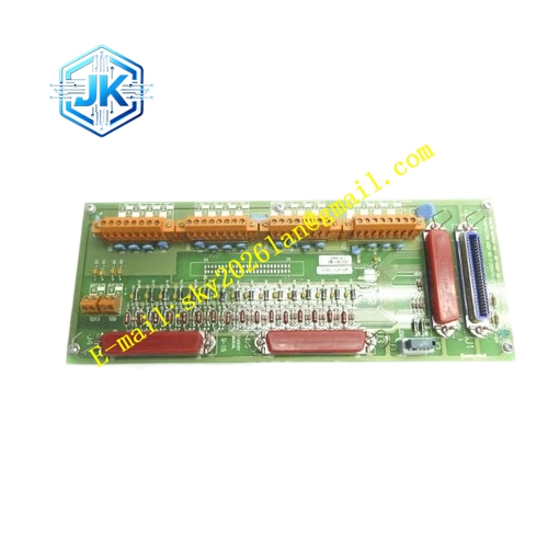
Structural Features Standard European pluggable card structure, compatible with standard UCN I/O rack slots. Front panel is equipped with operation indicator light, general fault indicator light and group status indicator lights. Detachable terminal block at the front end with clear channel number and polarity marking. Gold-plated back edge fingers connect to the UCN rack backplane bus. Analog signal wiring area is separated from digital logic area to reduce crosstalk.
Working Principle Field sensor signals are transmitted to the module terminals. Signals pass through isolation and filtering circuits before entering the ADC chip. The analog quantity is converted into digital sampling values. The on-board MCU converts raw sampling data into engineering values according to the configured range and sensor type. Valid data is packaged and transmitted to the HPM controller via the UCN bus. The module continuously monitors loop electrical characteristics and triggers alarm marks when abnormal states are detected.
Installation Requirements Insert the module vertically into the UCN rack slot and tighten the front panel fixing screws. Use shielded twisted pair cables for field wiring. The shield layer is grounded at the cabinet side only and kept floating at the field side. Signal cables shall be laid separately from high-power power cables and frequency converter output cables. Complete configuration download after wiring and verify the reading consistency between DCS screen and field instruments channel by channel. Confirm no condensation inside the cabinet in humid working conditions.
Precautions Do not connect high-voltage signals to the module terminals. High voltage surge will burn isolation chips and ADC circuits. Signal type configuration must match the actual field sensor, otherwise the measurement result will be completely invalid. The module cannot be directly used for high-speed pulse counting. Regular inspection of terminal blocks is required in corrosive environments to avoid oxidation and poor contact.







