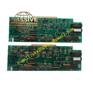
Description
Eaton MPB1-TP
Technical Specifications Three-phase current and voltage measurement; supply voltage 24VDC or 110/230VAC; adjustable overload thermal curve; phase loss, phase unbalance, earth fault protection; programmable relay trip and alarm output; 4-20mA analog output; DIN rail mounting; IP20 protection rating.
Functional Features Thermal overload protection with adjustable motor thermal memory; phase loss and phase unbalance detection; overcurrent and locked rotor protection; earth fault leakage current monitoring; separate alarm relay and trip relay output; parameter configuration via front keypad; fault value and fault type stored in memory; LED status indication.
Application Scenarios Factory conveyor motor protection; pump and fan motor control cabinet; water treatment motor control; oil and gas auxiliary motor protection; HVAC large fan motor protection.
Performance Parameters Operating ambient temperature -20℃ to +60℃; storage temperature -40℃ to +85℃; relative humidity 5% to 95%, no condensation; comply with IEC 60947 motor protection standard.
Material Composition Flame-retardant plastic DIN rail housing; multi-layer measurement PCB; current and voltage sampling components; microprocessor chip; electromechanical trip and alarm relays; brass nickel-plated screw terminals; LED status indicators.
Structural Characteristics Narrow rectangular DIN rail module; front panel operation keypad and LED status indicators; upper and lower terminal blocks for CT current, power supply and relay trip wiring; internal isolation between high voltage sampling circuit and low voltage processing circuit.
Working Principle Current transformers and voltage sensing circuit collect three-phase motor current and voltage signals. Sampled analog signal converts to digital data. Microprocessor calculates motor thermal state and detects phase unbalance, phase loss, overcurrent and earth fault. When measured value exceeds protection threshold, relay contact operates to trip motor contactor. Fault information saves into non-volatile memory.
Installation Requirements Mount relay on standard TS35 DIN rail inside control cabinet. Connect CT secondary wiring strictly following schematic. Wire trip relay circuit to motor contactor coil. Set motor rated current and protection thresholds via front keypad. Complete cabinet protective earthing and test protection function.
Usage Notes Do not short circuit CT secondary terminals when live. Check CT wiring polarity before commissioning. Backup protection setting parameters before firmware update. Inspect relay contact wear periodically.