Description
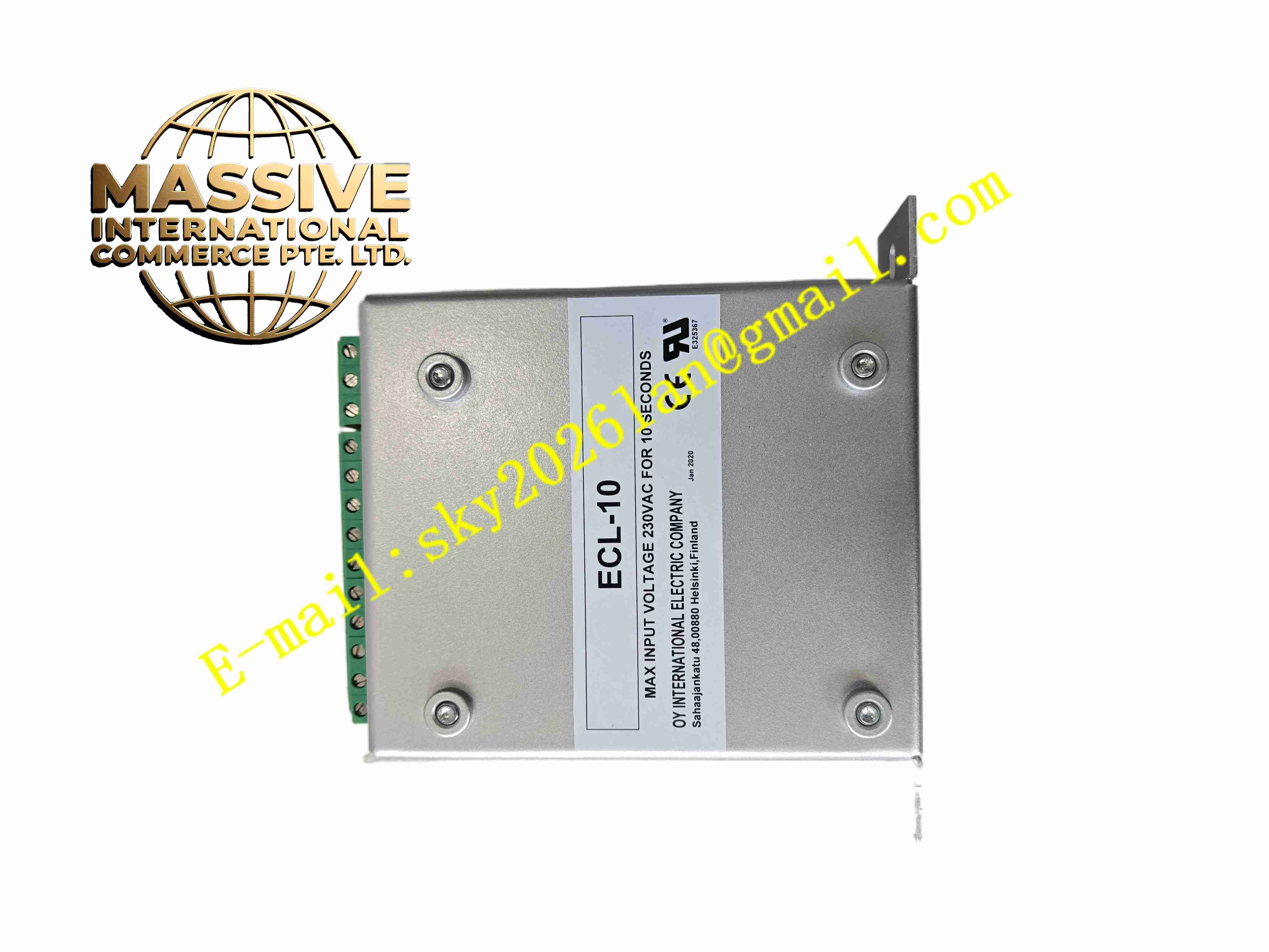
ECLIPTEK ECL-10
Technical Specifications:
- Product Type: Crystal oscillator (XO) module
- Supply Voltage: 3.3V or 5V DC
- Frequency Tolerance: ±20ppm at 25°C
- Operating Temperature: -40°C to +85°C
- Storage Temperature: -55°C to +125°C
- Output Logic: CMOS square wave output
- Load Capacitance: Standard CMOS load
- Aging Rate: Maximum 5ppm per year
- Package: Through-hole or SMD metal sealed package
Function Features:
- Stable fixed frequency clock reference for digital circuits
- Low phase jitter for serial communication and timing circuits
- Metal hermetic sealing to reduce frequency drift caused by humidity
- Low power consumption for embedded board applications
- Wide industrial temperature range
- Fast startup after power supply application
- Consistent frequency performance for long term operation
Application Scenarios:
- Industrial control PCB clock reference
- PLC and DCS controller main timing circuits
- Servo drive communication board timing
- Serial communication and fieldbus interface modules
- Medical, test and measurement electronic equipment
Material Composition:
- Housing: Metal hermetically sealed can package
- Quartz Element: AT-cut quartz crystal blank
- Internal PCB: Miniature FR4 circuit board with oscillator amplifier IC
- Terminals: Tin plated alloy lead pins
- Seal: Metal welded hermetic seal
Structural Features:
- Small cylindrical metal can package
- Through-hole pin-out for soldering onto printed circuit board
- Internal quartz crystal and oscillator IC enclosed inside sealed metal can
- Pin layout for power supply, ground and clock signal output
Working Principle: AT-cut quartz crystal resonates at fixed natural frequency when powered. The internal amplifier circuit maintains crystal oscillation and converts resonance signal into stable CMOS square wave clock output. The metal hermetic seal isolates quartz element from humidity and contaminants to preserve frequency stability over time. This clock signal supplies timing reference for digital logic, communication baud rate generation and data sampling circuits.
Installation Requirements:
- Solder oscillator pins directly onto host PCB pads
- Place component away from high heat power semiconductors
- Keep low speed clock trace short to avoid signal distortion
- Follow PCB layout ground plane recommendations for oscillator circuits
- Avoid mechanical shock during soldering and assembly
Usage Notes:
- Match supply voltage to oscillator specification
- Do not apply voltage exceeding rated maximum supply
- Avoid excessive soldering heat and prolonged high temperature exposure
- Prevent mechanical impact to metal can package
- Verify clock frequency on host board after soldering
- Keep component away from strong magnetic field sources