Description
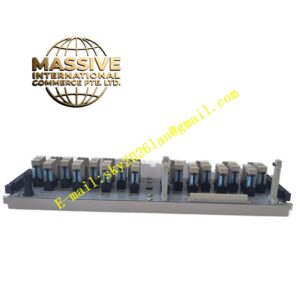
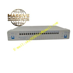
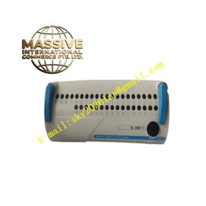
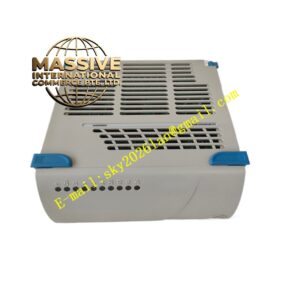
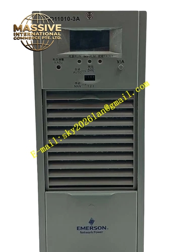
Emerson HD11010-3A
Technical Specifications: Rated voltage: 250 VAC Rated current per channel: 3 A Isolation voltage: 1500 VAC Operating temperature: -20 ℃ to 60 ℃ Storage temperature: -40 ℃ to 85 ℃ Relative humidity: 5% to 95% non-condensing
Functional Features: Screw type terminals for field cable termination. Independent replaceable fuse for each signal channel. Built-in surge suppression components for signal protection. Channel marking printed on terminal block. Reserved test points for signal measurement. Mechanical locking structure for cable entry. Supports DIN rail mounting.
Application Scenarios: Field instrument signal wiring terminal for petrochemical plant, temperature and pressure transmitter signal transfer terminal, power plant auxiliary equipment signal wiring, water treatment analog signal terminal assembly, pulp and paper mill field signal junction unit.
Performance Parameters: Terminal contact resistance less than 10 milliohm Vibration resistance: 10 Hz to 150 Hz, 0.5 g Shock resistance: 10 g peak acceleration, 11 ms duration MTBF value: 222000 hours
Material Composition: Housing: UL94-V0 flame-retardant thermoplastic. Terminal screws: nickel-plated brass. Fuse holder: high-temperature resistant engineering plastic. Internal PCB: FR-4 glass fiber epoxy substrate. DIN rail spring clip: stainless steel.
Structural Features: Standard 35 mm DIN rail snap mounting structure. Front panel arranged with parallel screw terminals and fuse slots. Channel identification printed on front shell. Cable entry channel at bottom of housing. Ventilation grooves on shell surface.
Working Principle: Field instrument signal cables connect to front screw terminals. Signal passes through fuse and surge protection component, then transmits to rear wiring interface connecting control I/O module. Fuse cuts off circuit automatically when over-current occurs to protect back-end I/O hardware.
Installation Requirements: Snap assembly onto standard 35 mm DIN rail. Tighten terminal screws with torque between 0.6 N·m and 0.8 N·m. Use shielded twisted pair cable for analog signal wiring. Separate signal cables and high voltage power cables. Cut off all related power before wiring operation.
Precautions for Use: Replace fuse only with specified rated current. Wear anti-static wristband when touching internal circuit. Inspect terminal tightness periodically. Do not install in environment with conductive dust. Stop using assembly if shell cracks or burn marks appear.