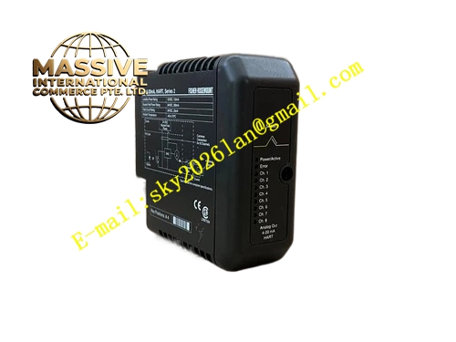
Description
Emerson HD22005‑3
Technical Specifications
- Input Voltage: 100VAC ~ 240VAC wide‑range AC input
- Output DC Voltage: 24VDC
- Rated Output Current: 5A
- Isolation: Galvanic isolation between AC input and DC output
- Operating Ambient Temperature: 0℃ ~ 60℃
- Storage Temperature: -40℃ ~ 85℃
- Relative Humidity: 5% ~ 95%, non‑condensing
- Protection Grade: IP20
- Mounting Form: DeltaV rack plug‑in card
- Built‑in EMI filter and multi‑protection circuit
- Front panel LED indicators for power status and fault alarm
Functional Features High‑efficiency AC‑DC conversion circuit provides stable 24VDC power for DeltaV rack backplane and field instrument loops.
EMI filter circuit suppresses high‑frequency interference from industrial power grid.
Built‑in hardware protection circuit cuts off output under overvoltage, overcurrent and overtemperature conditions.
Real‑time monitoring circuit samples output voltage and internal temperature continuously.
Hot‑swap mechanical design supports module replacement under non‑critical operating conditions.
Redundant parallel configuration achieves bumpless power switching.
Front panel LED lights display module running state and fault alarm directly.
Application Scenarios DeltaV DCS control cabinets in chemical plants, oil refineries, natural gas plants and thermal power plants.
It supplies 24VDC power for DeltaV rack backplane and two‑wire field transmitters connected to DeltaV I/O modules.
Performance Parameters DC output voltage maintains stable value in full working temperature range.
Output ripple keeps within specified limit under full load.
Protection circuit responds instantly when electrical parameters exceed safe threshold.
Diagnostic circuit detects power abnormality and uploads alarm without delay.
EMI filter effectively eliminates high‑frequency power grid noise.
Material Composition Flame‑retardant engineering plastic front housing.
Multi‑layer flame‑retardant glass‑fiber epoxy printed circuit board.
AC‑DC power conversion chips, monitoring microprocessor, EMI filter components and LED indicators.
Gold‑plated copper alloy backplane connector with anti‑oxidation coating.
High‑temperature resistant power capacitors and power semiconductors.
Metal heat sink for heat dissipation.
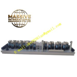
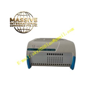
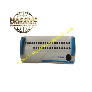
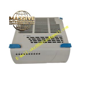
Structural Features Standard plug‑in card matching DeltaV rack slot dimension.
Front panel equipped with power normal LED and fault LED indicators.
Guide rails and spring latch fix module firmly inside control rack and resist vibration.
Rear gold‑plated multi‑pin connector connects to DeltaV rack backplane.
Internal metal heat sink absorbs heat generated by power components.
Shell heat dissipation slots realize natural air cooling.
Working Principle AC power enters module and passes through EMI filter to remove power grid high‑frequency noise.
AC‑DC conversion circuit converts AC to stable 24VDC direct current.
DC power transmits to rack backplane and field instrument loops through rear connector.
Sampling circuit continuously monitors output voltage, load current and internal temperature of module.
When overvoltage, overcurrent or overtemperature fault occurs, protection circuit cuts off DC output immediately. The module uploads fault alarm message to DeltaV operator station via backplane bus.
Redundant power modules run in parallel to guarantee continuous power supply.
Installation Requirements Insert module along rack guide rail into designated DeltaV rack slot and lock mechanical latch.
Connect AC input cable to module power terminals and tighten terminal screws.
Separate AC power wiring from low‑voltage signal cables to avoid electromagnetic interference.
Reserve air circulation space around module and do not block heat dissipation slots.
Complete hardware identification and parameter configuration in DeltaV engineering workstation after installation.
Precautions for Use Take anti‑static protection during module handling, do not touch gold‑plated connector pins with bare hands.
Cut off AC input power before wiring modification.
Verify output voltage after module replacement.
Check terminal tightness and cable insulation during regular maintenance.
Do not input AC voltage exceeding rated range.
Do not disassemble module housing, internal power components cannot be maintained on site.