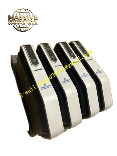
Description
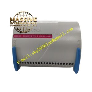
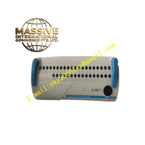
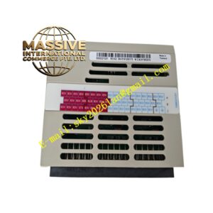
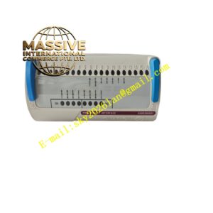
Emerson KJ4001X1‑JA1
Technical Specifications
- Supported Signal Type: 4‑20 mA analog signal with superimposed HART 7 protocol digital signal
- Terminal Connection Form: screw‑clamp terminal, compatible wire gauge 14‑24 AWG
- Maximum Field‑Loop Voltage: 30 VDC
- Operating Ambient Temperature: ‑40 °C ~ +70 °C
- Storage Temperature: ‑50 °C ~ +85 °C
- Relative Humidity: 5 %‑95 %, non‑condensing
- Airborne Contaminant Classification: ISA‑S71.04‑1985 Class G3
- Protection Class: IP20
- Shock Resistance: 10 g half‑sine pulse for 11 ms
- Vibration Resistance: 1 mm peak‑to‑peak amplitude for 2‑13.2 Hz; 0.7 g acceleration for 13.2‑150 Hz
- Mechanical Feature: rotary anti‑mismatch coding key, integral hot‑swap with matched HART‑enabled I/O‑module
- Safety Approval: ATEX, IECEx and FM certification for Zone 2 hazardous‑location deployment
Functional Features Optimized internal trace design preserves waveform integrity for HART digital signal superimposed on 4‑20 mA analog loop. Screw‑clamp terminals complete wiring termination for two‑wire HART smart transmitters and HART valve positioners. Rotary mechanical coding key prevents mismatched assembly with non‑HART‑compatible I/O‑module hardware. High‑reliability spring‑contact structure maintains stable electrical connection under cabinet vibration environment. Obtains bussed field‑power supply from I/O carrier‑base to deliver loop‑supply power for two‑wire HART field‑instruments. Supports integral removal and replacement with matched I/O‑module without disconnecting HART‑instrument field‑cables. Reserved marking area on housing surface supports HART‑loop identification label sticking for on‑site‑maintenance convenience. Complies with international hazardous‑area installation certification specifications.
Application Scenarios Petrochemical refineries, chemical‑processing plants and power‑generation‑unit control cabinets. Used for wiring termination of HART smart pressure, flow, level and temperature transmitters, as well as HART‑protocol smart valve positioners. Cooperates with M‑Series HART‑enabled analog‑input and analog‑output I/O‑modules.
Performance Parameters Internal circuit preserves HART digital‑signal transmission quality without waveform distortion within allowable loop‑impedance range. Terminal‑contact resistance keeps low‑stable value for whole equipment service‑life cycle. Mechanical key‑coding mechanism eliminates hardware mis‑assembly risk caused by human‑operation error. Electrical‑connection reliability remains stable under long‑term cabinet vibration working‑condition. Supports 7×24‑hour uninterrupted continuous industrial‑site running.
Material Composition Flame‑retardant high‑strength engineering‑plastic housing. Tin‑plated copper‑alloy screw‑clamp terminal contact components. HART‑signal‑optimized glass‑epoxy printed‑circuit substrate. Stainless‑steel mechanical locking hardware for fastening onto M‑Series carrier‑base.
Structural Characteristics Modular snap‑on construction for front‑face installation onto M‑Series I/O carrier‑base. Front‑plane arranged screw‑clamp terminal groups for HART two‑wire instrument loop wiring. Rotary coding dial located on side wall for hardware‑compatibility setting. Rear‑side contact assembly precisely mates with front‑side contact points of HART‑enabled M‑Series I/O‑module. Side‑mounted locking latches fasten terminal‑block unit firmly onto carrier‑base front plane. Blank marking zone reserved on housing surface for HART‑loop identification tagging.
Working Principle Two‑wire HART smart‑instrument field‑cables terminate onto KJ4001X1‑JA1 front‑side screw‑clamp terminals. Mixed 4‑20 mA analog signal and superimposed HART digital‑signal transmits through optimized‑layout internal traces of terminal‑block unit, signal waveform keeps undistorted. Composite signal passes rear‑side contact assembly and enters corresponding channel circuit of plugged‑in M‑Series HART‑enabled I/O‑module. Bussed field‑power supply delivered by carrier‑base provides loop‑supply power source for connected two‑wire HART field‑instruments through terminal‑block internal traces. Rotary mechanical coding dial defines compatible HART‑type I/O‑module hardware and blocks mismatched non‑HART‑module installation. This terminal‑block belongs to passive wiring hardware without built‑in HART‑modem chipset.
Installation Requirements Snap terminal‑block assembly onto target slot of M‑Series I/O carrier‑base, engage side locking latches until audible click‑in engagement. Set rotary mechanical coding‑key strictly according to specification of paired HART‑enabled I/O‑module hardware before inserting I/O‑module. Field‑instrument cables adopt HART‑specification compliant shielded twisted‑pair cables. Field‑cable conductor gauge stays within 14‑24 AWG range, tighten every terminal‑screw to specified torque‑value. Complete all HART‑instrument wiring work under field‑loop power‑off condition. Check wiring after completion, ensure no bare copper wire strands exposed outside screw‑clamp terminal area. When deploying within Zone 2 hazardous classified locations, fully execute ATEX and IECEx installation‑manual requirements.
Usage Precautions Total HART‑loop impedance must satisfy HART physical‑layer specification to guarantee reliable digital‑signal communication. Do not apply field‑circuit voltage exceeding 30 VDC rating onto terminal‑block channels. Check terminal‑screw tightening‑torque periodically in plant maintenance cycle. Rotary key‑setting must match hardware‑type of paired HART‑enabled I/O‑module. De‑energize field‑loop power supply before removing terminal‑block assembly. Do not disassemble terminal‑block housing; no internal components can be maintained or replaced by end‑user.