Description
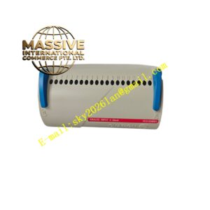
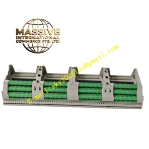
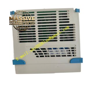
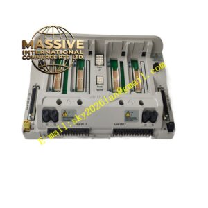
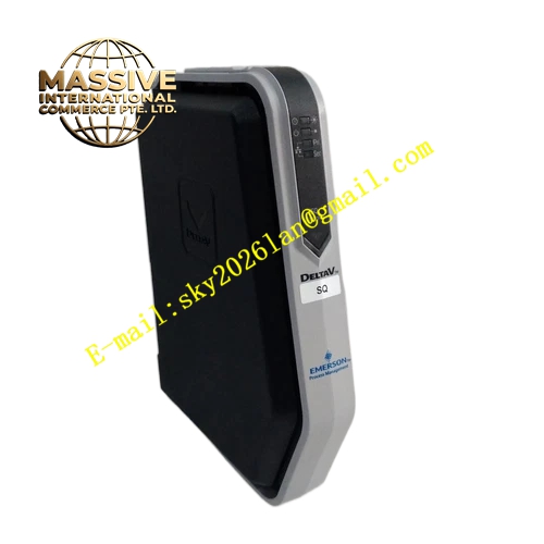
Emerson SE3008
Technical Specifications
- Channel configuration: 8‑channel programmable composite discrete I/O channels
- Input signal type: 24 VDC dry‑contact passive signal
- Output type: independent mechanical relay contact output
- Channel‑to‑system isolation voltage: 1500 V
- Operating temperature: 0 °C‑60 °C
- Signal sampling cycle: less than 10 ms
- Single‑channel relay rated load: 240 VAC / 2 A
Functional Features Every channel uses independent opto‑coupler isolation separating field loop and system circuit, eliminating ground‑loop interference and high‑frequency noise. Each channel equips individual LED indicator showing real‑time on‑off condition. Built‑in channel overload protection, short‑circuit protection and open‑loop fault diagnosis detect field wire break, short‑circuit and load abnormality. Under redundant cabinet configuration it supports hot‑swap replacement without disturbing other channels or whole‑system operation. Channel direction can be configured as input or output according to actual field requirements.
Application Scenarios Used for switch‑signal acquisition and equipment on‑off control inside petrochemical plants, thermal power stations, natural gas compressor stations, water‑treatment projects and general machinery automation lines. Typical tasks include valve‑position feedback monitoring, motor start‑stop logic control, equipment limit interlock signal collection, site alarm lamp driving and interlock‑signal transmission.
Performance Parameters
- Complete accuracy for switch‑state judgment
- Channel response time below 10 ms
- Long relay mechanical service life suitable for frequent switching
- Strong suppression capability for industrial surge and electromagnetic interference
Material Composition Outer housing is high‑strength flame‑retardant ABS plastic with impact‑resistance and corrosion‑resistance properties. Inner circuit board is industrial flame‑retardant PCB. Core components contain stable opto‑coupler chips, industrial signal relays, sampling resistors and protective capacitors. Backplane connector uses gold‑plated contacts for stable long‑term connection.
Structural Characteristics Standard plug‑in card form‑factor for cabinet slot installation. Front panel integrates field‑wiring terminal blocks and channel‑status LED lamps for convenient field debugging and status observation. Mechanical lock buckle stops module loosening caused by equipment vibration. Internal circuit layout creates isolated zone for every channel to avoid cross‑channel signal crosstalk. Compact overall dimension supports dense cabinet arrangement.
Working Principle For input channels: passive dry‑contact signal from field hardware passes terminal block into opto‑isolation circuit. After photoelectric conversion and signal shaping, standardized digital signal transmits onto system bus for upper‑level controller reading. For output channels: control commands arrive via backplane bus and energize corresponding internal relay coil. Relay contacts close or open to switch field equipment power circuit. Each channel operates independently; fault occurring on one channel does not influence remaining working channels.
Installation Requirements Insert module into matched cabinet backplane slot and engage locking buckle. Field signal cables shall be shielded twisted‑pair; cable shield connects to cabinet ground bar following official specification. Signal wiring and high‑voltage power wiring must run inside separate cable ducts to avoid electromagnetic coupling interference. Maintain cabinet environment dry, low‑dust and free of corrosive vapor. Leave proper cooling clearance between adjacent modules.
Use Precautions Never feed high‑voltage signals exceeding rated range into digital channels, otherwise opto‑coupler and relay hardware suffer permanent burnout. Verify wiring definition and channel correspondence fully before power‑on. Periodically inspect contact wear for channels performing frequent switching actions. Prevent output channels running continuously under overload. Avoid deployment in environments with conductive dust, violent vibration or intensive electromagnetic fields.