Description
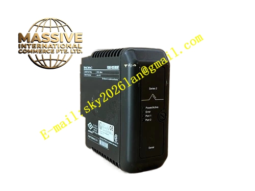
Emerson VE4001S2T1 12P0549X112
Technical Specifications
- Supported Signal: Discrete safety digital output switching signal
- Built-in Surge Suppression Protection Components
- Operating Ambient Temperature: 0℃ ~ 60℃
- Storage Temperature: -40℃ ~ 85℃
- Relative Humidity: 5% ~ 95%, non-condensing
- Mounting Method: DIN rail installation inside safety control cabinet
- Screw type wiring terminals
- Mechanical Matching: Compatible with DeltaV SIS digital output plug-in modules
- Protection Grade: IP20
Functional Features Screw terminals facilitate wiring of field safety load cables and support disassembly during safety system maintenance. Built-in surge suppression components absorb instantaneous voltage spike generated by inductive loads such as solenoid valves. Internal PCB traces transmit safety switching signals downward from the upper SIS digital output module to field wiring terminals. Precise mechanical positioning ensures stable electrical contact between terminal base and SIS digital output module. Modular structure allows independent replacement of terminal base without removing the upper SIS module under permitted maintenance conditions. Channel isolation design prevents interference between different safety output loops.
Application Scenarios DeltaV SIS safety control cabinets in chemical plants, oil refineries and natural gas processing facilities. It cooperates with DeltaV SIS digital output modules to control safety solenoid valves, safety relays and emergency shutdown equipment in emergency shutdown loops.
Performance Parameters Internal signal traces maintain low signal attenuation for safety switching signal transmission. Surge protection components suppress back electromotive force surge from inductive safety loads effectively. Screw terminals keep stable electrical connection under long-term cabinet vibration. Contact pins maintain reliable connection after repeated plugging of SIS digital output modules. Isolation circuit eliminates signal cross-talk between adjacent output channels.
Material Composition Main body substrate adopts flame-retardant PA engineering plastic. Nickel-plated copper alloy screw terminals. Multi-layer glass fiber epoxy PCB substrate. Solid-state surge suppression components. Anti-oxidation plated metal positioning contact pins.
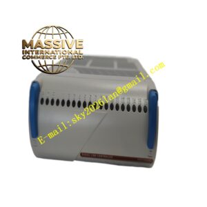
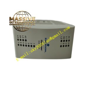
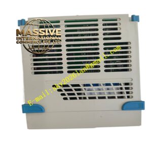
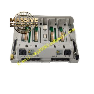
Structural Features DIN rail fixed base structure. Front side equipped with multiple screw terminals for field safety load cables. Top metal contact pins mate with DeltaV SIS digital output module bottom connector. Positioning buckle locks terminal base and aligns with plug-in SIS modules. Integrated wiring channel guides safety load cables neatly inside safety cabinet.
Working Principle Safety switching control signals from SIS digital output module transmit downwards through top metal contact pins to internal PCB traces of terminal base. Signals pass through surge suppression circuit and reach screw wiring terminals connected to field safety loads. When inductive safety load cuts off power, back electromotive force surge appears on field cables. Surge suppression components absorb voltage pulse to protect SIS module circuit. Screw terminals transmit safety on-off signals to field safety solenoid valves and safety relays through external cables.
Installation Requirements Mount terminal base on standard DIN rail inside safety control cabinet and fasten mounting buckle. Connect external safety load cables and tighten each terminal screw to specified torque. Install freewheeling diode for field inductive safety loads to assist surge absorption. Check full contact between top pins and SIS digital output module after module insertion. Keep safety output wiring separated from high-voltage power wiring.
Precautions for Use Cut off field safety load power before wiring adjustment. Inspect terminal tightness and cable insulation regularly. Do not apply overvoltage to signal terminals. Keep contact pins clean without metal scraps and dust. Do not alter internal circuit of terminal base.