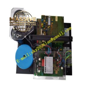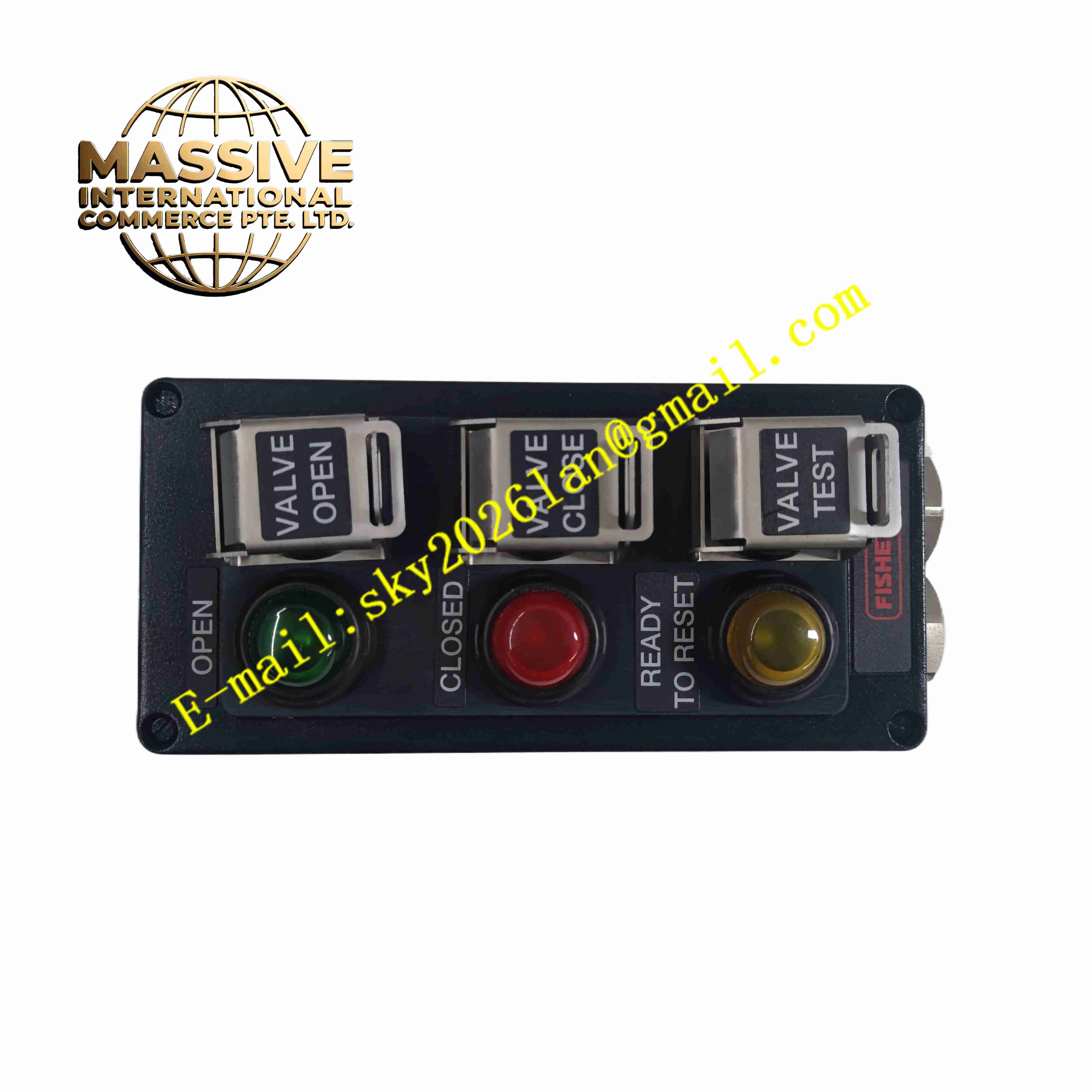
Description
Fisher LCP100
Technical Specifications
- Product type: Liquid level controller
- Measured: Liquid level
- Range: Selected by flange and span
- Output: Pneumatic signal or relay contacts
- Medium temperature: -40 °C to +350 °C
- Process connection: Flanged
- Protection: IP66
- Explosion protection: Ex d flameproof
- Temperature: -40 °C to +70 °C
- Storage: -50 °C to +85 °C
- Humidity: 0 to 100 %
- Installation: Side flange / top mount
- Certifications: ATEX, FM, CSA
Functional Features
- Continuous tank level measurement and switch alarms
- High and low level switch outputs
- Pneumatic control output to control valves
- Multi-spot torque balance for stable measurement
- Flanged process connection for high pressure and temperature
- Flameproof design for hazardous areas
- IP66 for outdoor weather
- Local pointer level indication
- Adjustable setpoint in field
- Long maintenance-free life
Application Scenarios
- Petrochemical tank level monitoring and interlock
- Chemical reactor level control
- Oil/gas separator level alarm
- Refinery column level measurement
- Offshore platform hazardous area level control
Materials and Construction
- Process flange: Carbon steel / stainless steel
- Measuring element: Displacer / float
- Housing: Aluminum / stainless die-cast
- Spring: Stainless steel
- Gasket: Graphite spiral wound
- Gauge: Glass pointer dial
Structural Features
- Side flange to vessel
- Displacer chamber vertical, internal float follows level
- Gauge head on top, lever-spring mechanism
- Glass pointer indicates level
- Wiring compartment separately sealed
- Process flange per pressure class
Working Principle Level in the displacer chamber matches vessel level; the float rises and falls with level, moving a lever that deflects a bourdon/spring tube in the head, driving a pointer to indicate level. When level reaches a switch point it trips a mechanical switch, outputting relay contacts for interlock. In pneumatic output mode the lever adjusts a nozzle-flapper to output a pneumatic signal proportional to level for control valves.
Installation Requirements
- Flange horizontal or vertical on vessel side
- Open equalizing valves between chamber and vessel
- Medium density matches design density
- Mount head vertical
- Temperature -40 °C to +70 °C
- Calibrate level zero after power-up
- Design tracing heat per medium pour point
Precautions
- Medium density changes affect accuracy
- Keep chamber free of gas and sediment
- Periodically drain chamber
- Protect gauge glass from impact
- Follow explosion-protection rules in hazardous areas
- Store spares in dry environment