Description
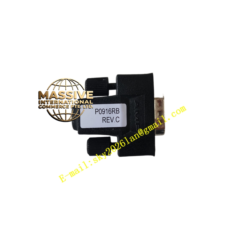
Foxboro RH916RB
Technical Specifications:
- Type: Digital Input Terminal Assembly (16 or 32 channels depending on configuration)
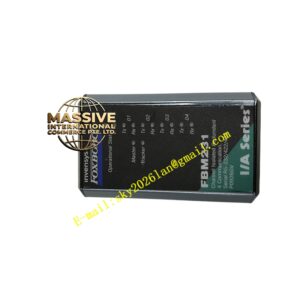
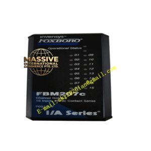
- Associated Module: FBM241 / FBM207
- Input Voltage: 24 V DC (Contact Sense)
- Filtering: Software configurable input filtering (debounce)
- Isolation: Opto-isolation channel-to-channel and channel-to-ground
- Termination: Screw terminals
- Environmental Rating: G3
- Operating Temperature: -40 °C to +70 °C
Functional Features:
- Wet or dry contact sensing capability
- High noise immunity due to optical isolation and filtering
- Status LEDs for immediate field troubleshooting
- Pluggable design for easy module replacement
- Built-in overvoltage protection on input channels
Application Scenarios:
- Monitoring valve position feedback (open/closed)
- Sensing motor starter status
- Emergency stop input monitoring
- General-purpose discrete sensing in manufacturing and process control
Performance Parameters:
- High input impedance to minimize current draw from field devices
- Fast response time configurable from milliseconds to seconds
- High reliability with long contact life expectancy
Material and Structural Characteristics:
- Rugged polycarbonate enclosure to protect internal circuits
- Corrosion-resistant terminal screws
- Internal circuit board conformal coated for moisture resistance
Working Principle:
The terminal assembly receives a voltage signal (24 V DC) from a field device when a contact closes. This signal is passed through an optocoupler to electrically isolate the field side from the system side. The isolated signal is then read by the digital input module as a logic high or low state.
Installation Requirements:
- Connect field devices ensuring the correct polarity of the 24 V DC sense voltage
- Verify that the voltage level from the field device matches the input requirements
- Route wiring away from high-voltage cables to avoid noise
Usage Notes:
- Use shielded cable for long run distances to prevent electromagnetic interference
- Periodically verify input status against physical field device state
- Ensure that field contacts are debounced mechanically if necessary, or use module filtering