Description
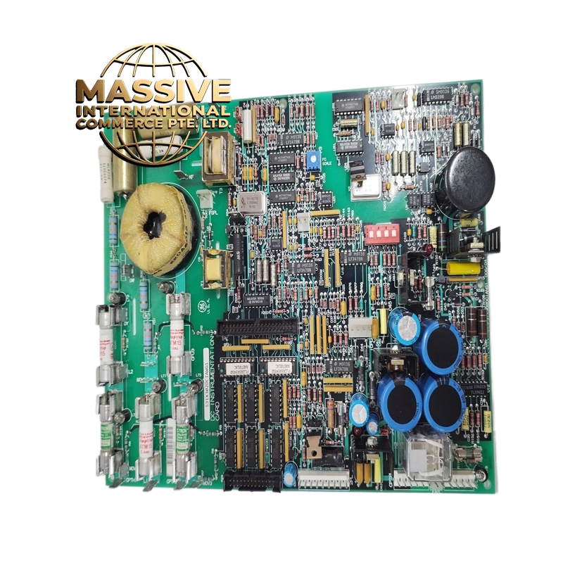
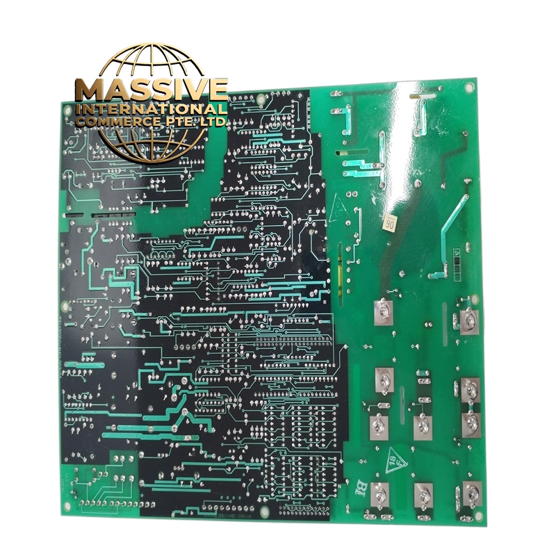
GE 531X302DCIAWG1 Technical Specifications:
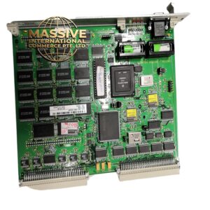
- Product Type: DC Instrument Board / DC Power Distribution Module.
- Manufacturer: General Electric (GE).
- System Series: Field Control / Switchgear Auxiliary Systems.
- Input Power: Accepts standard AC mains or primary DC supply.
- Output: Regulated DC bus for control and protection circuits.
- Backup Integration: Direct interface with station battery banks for uninterrupted power.
Functional Features:
- Uninterrupted Power Supply: Guarantees continuous DC power to protection relays and trip circuits during AC blackouts.
- Signal Distribution: Distributes DC power to panel-mounted signal lights, annunciators, and smart monitoring devices.
- Circuit Protection: Integrated fusing and overcurrent protection for individual output branches to isolate faults.
- Voltage Regulation: Maintains stable DC output voltage despite fluctuations in the primary power source or battery discharge.
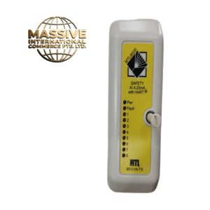
- Status Monitoring: Provides local visual indication of power presence, battery status, and fuse health.
Application Scenarios:
- High-voltage and medium-voltage electrical substations.
- Industrial power distribution switchgear and motor control centers (MCCs).
- Backup power systems and emergency diesel generator panels.
- Critical infrastructure requiring fail-safe control power.
Performance Parameters:
- Reliability: Engineered for 24/7 continuous operation with zero downtime.
- Transient Immunity: Highly resistant to voltage spikes and electrical noise common in high-voltage environments.
- Load Capacity: Sized to handle the inrush and steady-state currents of multiple protection relays and indicators.
- Efficiency: Low power loss design to minimize heat generation within enclosed panels.
Material Composition & Structural Characteristics:
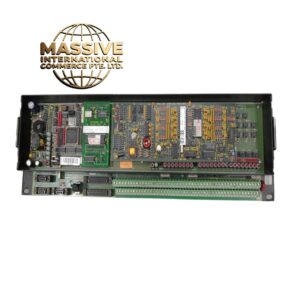
- Chassis: Heavy-duty metal enclosure providing EMI shielding and mechanical protection.
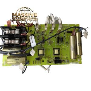
- Internal Components: Industrial-grade power rectifiers, filter capacitors, and high-rupturing-capacity (HRC) fuses.
- Wiring: Internal busbars and heavy-gauge wiring to handle high DC currents with minimal voltage drop.
- Terminals: Clearly labeled, barrier-type terminal blocks for safe and organized field wiring.
Working Principle: The board receives primary power and conditions it into a stable DC voltage. Under normal conditions, it powers the connected DC loads while simultaneously monitoring the battery bank. If the primary power fails, internal diode-ORing or solid-state switching logic instantly transfers the load to the battery source without any interruption. The board continuously regulates the output to protect sensitive microprocessor-based relays from overvoltage.
Installation Requirements:
- Mounting: Securely bolt the board to the designated mounting rails within the switchgear panel.
- Battery Connection: Connect to the station battery bank using appropriately sized, fused cables.
- Load Wiring: Connect DC loads to the designated output terminals, strictly observing positive and negative polarity.
- Grounding: Ensure the board chassis and DC negative are properly grounded according to site electrical standards.
Usage Precautions:
- DC Arc Hazard: Exercise extreme caution when working on DC circuits, as DC arcs are difficult to extinguish. Always de-energize before servicing.
- Polarity Check: Double-check all connections before applying power; reverse polarity can instantly destroy protection relays.
- Fuse Replacement: Only replace blown fuses with identical type, rating, and interrupting capacity. Investigate the root cause of the fault first.
- Battery Maintenance: Regularly test the connected battery bank, as the board’s backup capability is entirely dependent on battery health.