Description
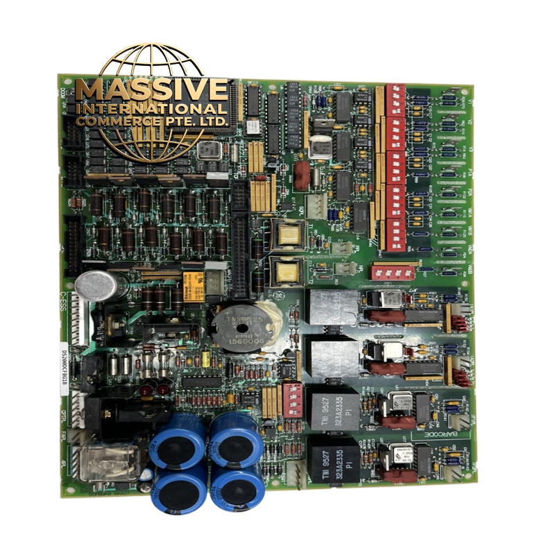
GE DS3800HFPB1F1E
Technical Specifications:
- Manufacturer: General Electric (GE).
- Product Type: RST Analog I/O Board.
- System Series: Mark V Speedtronic Gas Turbine Control System.
- Country of Origin: United States.
- Signal Types Supported: LVDT inputs, servo valve outputs, thermocouple inputs, 4-20 mA inputs/outputs, vibration inputs, relay driver outputs, pulse inputs, voltage inputs, generator, and line signals.
- Hardware Jumpers: J1 and J2 (milliamp output circuit selection), J5 and J6 (mA output range configuration for 20 mA or 200 mA), J7 (RS232 port card testing), J8 (oscillator startup).
Functional Features:
- Signal Conditioning: Precisely scales and conditions 4-20 mA input signals, including critical parameters like compressor stall detection and fuel flow pressure.
- Core Integration: Seamlessly processes signals from terminal boards across multiple I/O cores to ensure comprehensive turbine monitoring.
- Data Bus Communication: Utilizes the 3PL connector as a data bus to connect with STCA, TCQA, and TCQE boards, transmitting conditioned signals to the COREBUS.
- Specialized Signal Routing: Uses the JE connector to send and receive generator and line signals, pulse signals, and servo valve driver outputs to and from the TCQC board.
Application Scenarios:
- Primary control and monitoring of heavy-duty industrial gas turbines.
- Power generation plants utilizing GE Mark V turbine control systems.
- Precision actuation and monitoring of fuel valves and steam valves via LVDT and servo valve outputs.
- Real-time vibration and thermal monitoring within turbine enclosures.
Performance Parameters:
- Input/Output Capacity: Handles multiple concurrent analog channels for comprehensive engine management.
- Signal Accuracy: High-precision scaling and conditioning to ensure accurate fuel flow and valve positioning.
- Processing Speed: Rapid signal conditioning and transmission via the 3PL data bus to support real-time turbine protection and control.
- Reliability: Industrial-grade design built to withstand the harsh electromagnetic and thermal environments of power generation.
Material Composition & Structural Characteristics:
- Circuit Board: Multi-layer industrial printed circuit board (PCB) with high-density surface-mount components.
- Connectors: Robust industrial connectors including 2PL (power distribution from TCPS), 3PL (data bus), JE, JF, JG, and TBQA/TBQC terminal interfaces.
- Hardware Configuration: Equipped with accessible hardware jumpers (J1, J2, J5, J6, J7, J8) for custom field configuration and testing.
- Thermal Management: Designed with appropriate component spacing and board layout to dissipate heat generated by analog signal processing.
Working Principle: The DS3800HFPB1F1E receives raw analog signals from various field sensors connected to the terminal boards. The board’s internal circuitry scales and conditions these signals into standardized formats. For example, 4-20 mA inputs are processed for system use, while LVDT and thermocouple signals are prepared for digital conversion. The conditioned signals are then routed via the 3PL connector to the STCA board and onto the COREBUS for the main processor. Simultaneously, control outputs are routed via the JE connector to drive physical actuators and monitor generator outputs.
Installation Requirements:
- Slot Placement: Must be correctly installed in the designated I/O core slots (R1, R2, or R3) within the Mark V rack.
- Power Connection: Ensure the TCPS board properly distributes power via the 2PL connector to the core and this analog I/O board.
- Jumper Configuration: Carefully set hardware jumpers J1, J2, J5, and J6 according to the specific application requirements for milliamp output circuits and current ranges before powering up the system.
- Cable Routing: Connect the JE, JF, and JG connectors to their respective TCQC and TBQ terminal boards, ensuring secure locking mechanisms are engaged.