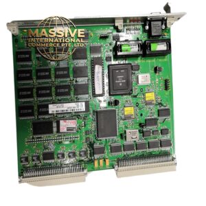
Description
GE IC660EBD025
- Technical Specifications:
- Channels: 2 independent high-speed counter channels
- Input Type: Differential 24VDC (A/B phase)
- Maximum Counting Frequency: Up to 200 kHz per channel
- Counter Range: 32-bit signed counter (−2,147,483,648 to +2,147,483,647)
- Input Voltage: 24VDC nominal, with differential signal detection
- Isolation: Optically isolated from backplane
- Power Consumption: Approximately 1.5W per module
- Operating Temperature: 0°C to 60°C (32°F to 140°F)
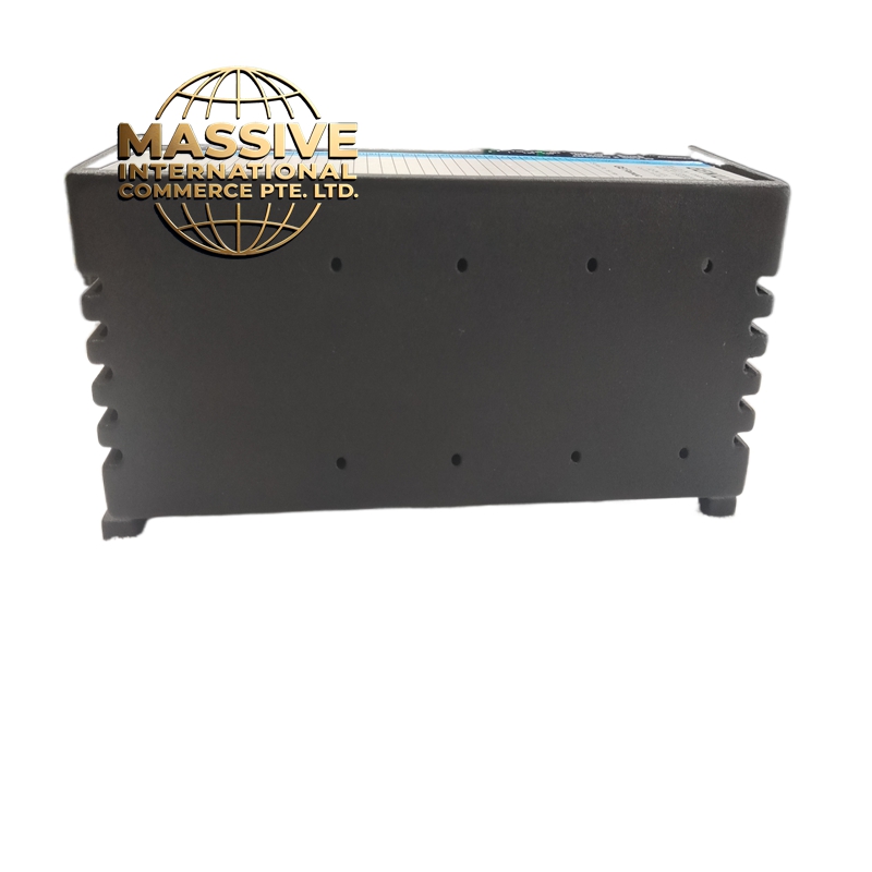
- Dimensions: Standard IC660 module form factor (approx. 165mm x 98mm x 120mm)
- Functional Features:
- Supports quadrature encoder input (A/B phase) for position tracking
- Supports up/down counting mode for bidirectional encoder feedback
- Provides hardware-based counting — no CPU scan cycle dependency
- Supports modulo counting (reset at preset value)
- Supports latch and capture functions for snapshot readings
- Compatible with GE Proficy Machine Edition and VersaMax Logic Developer software
- Application Scenarios:
- Conveyor belt speed and length measurement
- Rotary encoder position feedback for servo/stepper motors
- Web tension control in printing and packaging
- Cut-to-length applications
- Flow meter pulse counting
- Performance Parameters:
- Counting Resolution: Single pulse per count (1x mode), or 4x edge detection
- Response Time: Less than 1 microsecond per count
- Signal Integrity: Differential input rejects common-mode noise up to 1500V
- Backplane Bus: VersaMax high-speed I/O bus, 10Mbps data rate
- Material Composition:
- Housing: Flame-retardant ABS plastic, UL94 V-0 rated
- PCB: FR-4 glass epoxy, conformally coated
- Connectors: Gold-plated pin connectors for backplane interface
- Isolation Barrier: Opto-isolators (LED + phototransistor)
- Structural Features:
- Standard IC660 DIN-rail mountable module
- Front-facing LED indicators for channel status (power, count, fault)
- Backplane connector with keyed alignment for correct insertion
- Terminal blocks for field wiring (screw-type, 18-22 AWG wire compatible)
- Working Principle:
- The module receives differential A/B phase signals from incremental encoders or pulse generators. An internal FPGA/ASIC processes the quadrature signals, determining direction and accumulating counts in a 32-bit register. The CPU reads the counter value via the backplane bus during each scan cycle. Hardware-based counting ensures no counts are missed even at high speeds.
- Installation Requirements:
- Mount in a VersaMax I/O rack (IC695 or IC697 chassis)
- Ensure proper backplane alignment and firm seating
- Use shielded twisted-pair cable for encoder connections
- Ground the shield at one end only (chassis ground)
- Maintain minimum 10mm clearance between modules for airflow
- Usage Precautions:
- Do not exceed 24VDC input voltage — overvoltage will damage the opto-isolators
- Do not connect single-ended signals to differential inputs without proper termination
- Keep signal cables away from high-power motor drives (minimum 30cm separation)
- Verify encoder signal voltage matches module specification before connection
- Use external pull-up/pull-down resistors only if recommended in the datasheet
- Do not hot-swap the module — power down the rack before insertion/removal