
Description
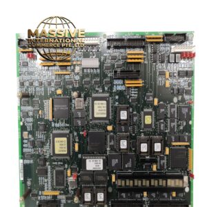
GE IC660ELB921H
- Technical Specifications:
- Channels: 16 independent digital input channels
- Input Type: 24VDC sinking (NPN)
- Input Voltage Range: 18VDC to 30VDC (logic high), 0V to 5VDC (logic low)
- On/Off Threshold: 10VDC turn-on, 3VDC turn-off
- Input Current: Approximately 3mA per channel (sinking)
- Response Time: 1ms ON→OFF, 10ms OFF→ON
- Isolation: 500V RMS optical isolation per channel group
- Power Consumption: Approximately 4W
- Operating Temperature: 0°C to 60°C
- Functional Features:
- 16 channels with individual LED indicators
- NPN/sinking input type — compatible with most global sensors
- Channel grouping: 2 groups of 8 channels with common isolation barriers
- Diagnostic capability via front-panel LEDs
- Backplane-powered design
- Application Scenarios:
- High-density input applications in packaging machines
- Multi-sensor monitoring in automotive assembly
- Process control panel input aggregation
- Machine safety interlock circuits
- Batch counting and event logging
- Performance Parameters:
- Input Impedance: ~5kΩ typical
- Isolation Voltage: 500V RMS (field to logic)
- Common Mode Rejection: >1000V
- Bus Speed: 10Mbps VersaMax backplane
- Material Composition:
- Housing: Flame-retardant ABS, UL94 V-0
- PCB: 4-layer FR-4, RoHS compliant
- Terminals: Tin-plated copper screw terminals
- Isolation: Opto-couplers with LED + phototransistor pairs
- Structural Features:
- Standard IC660 module size
- 16 red LED status indicators on front panel
- Two isolation barrier zones (channels 1-8 and 9-16)
- DIN-rail or chassis mount
- Working Principle:
- NPN sensors switch the 0V (ground) side. When active, the sensor pulls the input terminal to ground. The module detects this as a closed circuit through the opto-isolator’s input LED, which activates the phototransistor on the logic side, signaling a logic “1” to the CPU.
- Installation Requirements:
- Mount in IC695 or IC697 VersaMax chassis
- Wire NPN sensors: sensor output to module input, sensor ground to common
- Use 20-26 AWG wire
- Common terminal must be connected to 0V/ground
- Usage Precautions:
- Only use with NPN (sinking) sensors — PNP sensors will not function
- Do not leave input channels floating — always wire to a defined state
- Ensure common ground connection is solid
- Avoid wiring near high-current cables (>30cm separation)