Description
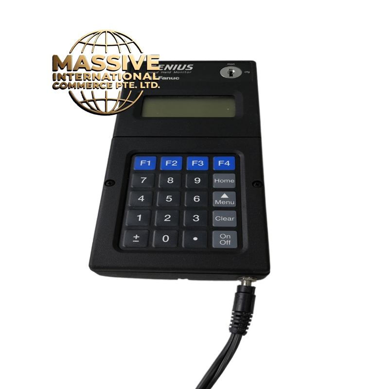
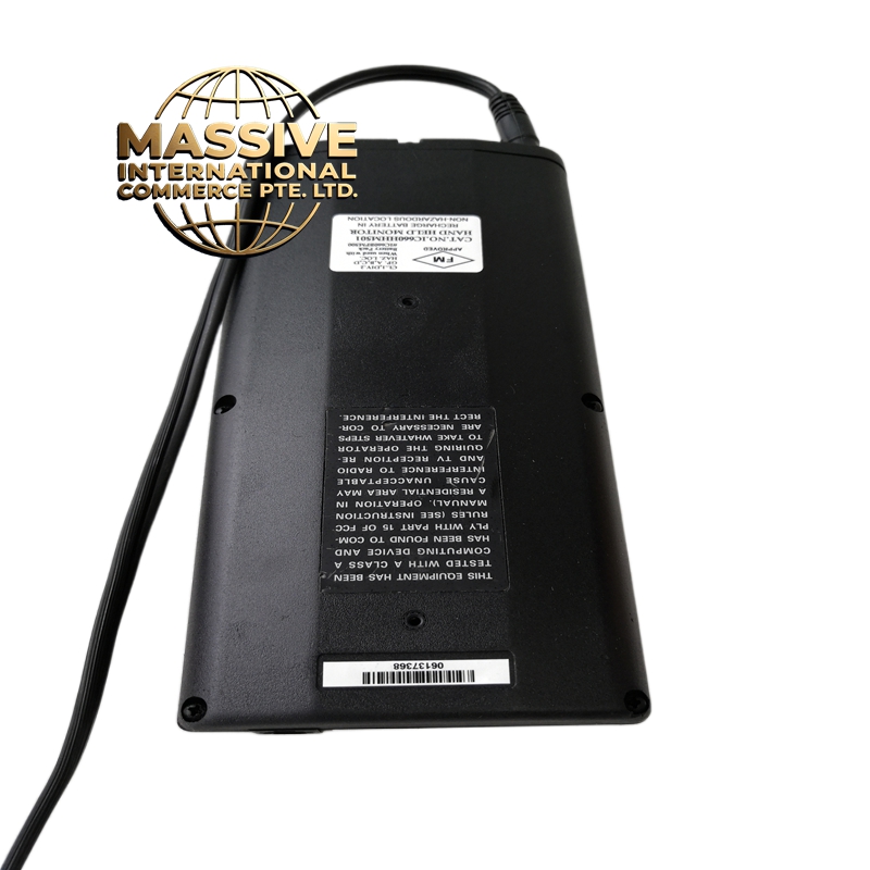
GE IC660HHM501N
- Technical Specifications:
- Channels: 4 independent pulse output channels
- Output Type: NPN transistor (open collector), 24VDC
- Maximum Pulse Frequency: 100 kHz per channel
- Output Voltage: 24VDC (via external pull-up), 0V when active
- Output Current: 100mA per channel (maximum)
- Pulse Resolution: 1 microsecond minimum pulse width
- Isolation: Optically isolated, 500V RMS
- Power Consumption: ~2.5W
- Operating Temperature: 0°C to 60°C
- Functional Features:
- 4-axis independent pulse generation
- Supports PWM and PTO modes
- Hardware-based pulse generation — no CPU scan dependency
- Supports acceleration/deceleration profiles
- Compatible with GE Motion Control function blocks
- Diagnostic LEDs per channel
- Application Scenarios:
- Stepper motor speed and position control
- Servo drive pulse command generation
- Conveyor indexer control
- Textile machine yarn feed control
- Valve actuation timing
- Performance Parameters:
- Pulse Accuracy: ±1 count at 100kHz
- Rise/Fall Time: <1 microsecond
- Isolation: 500V RMS
- Bus Speed: 10Mbps VersaMax backplane
- Material Composition:
- Housing: Flame-retardant ABS, UL94 V-0
- Output Transistors: NPN Darlington pairs with built-in suppression diodes
- PCB: 4-layer FR-4, conformally coated
- Connectors: Backplane edge connector + screw terminals
- Structural Features:
- Standard IC660 module size
- 4 LED indicators (one per axis)
- Screw-terminal output connections
- DIN-rail mountable
- Working Principle:
- The CPU writes target pulse count and frequency to the module’s internal registers via the backplane bus. The module’s internal hardware generates the pulse train autonomously using a crystal oscillator. Each output transistor switches on/off to produce the pulse train. The CPU can update parameters in real-time without stopping the pulse output.
- Installation Requirements:
- Mount in VersaMax chassis
- Connect external 24VDC pull-up supply to each output (if not using internal)
- Use twisted-pair cable for pulse outputs to reduce EMI
- Keep pulse cables away from AC power lines
- Usage Precautions:
- Do not connect outputs directly to AC loads — transistor outputs are DC only
- Ensure external pull-up voltage does not exceed 30VDC
- Do not exceed 100mA per channel — use external relays for higher loads
- Add flyback diodes for inductive loads (solenoids, relays)
- Do not hot-swap