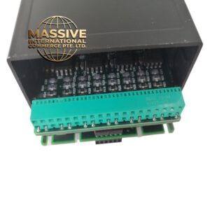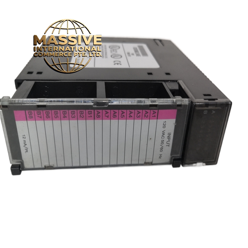
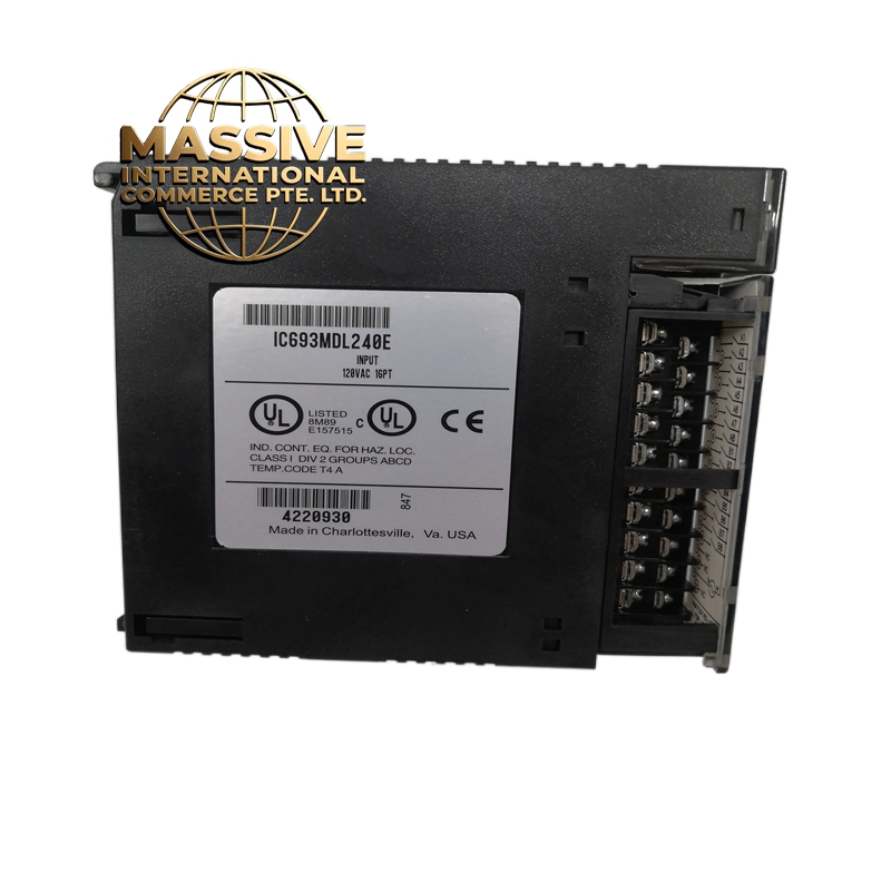
Description
GE IC693MDL240
- Technical Specifications:
- Channels: 8 independent relay output channels
- Output Type: Mechanical relay (SPDT — Single Pole Double Throw)
- Load Rating: 2A @ 250VAC or 2A @ 30VDC (resistive)
- Coil Voltage: 24VDC
- Contact Configuration: NO (Normally Open), NC (Normally Closed), COM (Common) per channel
- Switching Time: 10ms (typical), 5ms max
- Mechanical Life: 10,000,000 operations
- Electrical Life: 100,000 operations at full load
- Isolation: 500V RMS between channels and to backplane
- Power Consumption: ~8W (all 8 relays energized)
- Operating Temperature: 0°C to 60°C
- Dimensions: Full-width IC693 module
- Functional Features:
- 8 SPDT relay outputs — each channel has NO, NC, COM terminals
- LED indicator per channel (red) shows output state
- Backplane-powered — no external power supply needed for module logic
- Snubber circuit (RC network) across each relay contact for inductive load protection
- Compatible with all 90-30 CPUs via Genius Bus
- Supports forced output for troubleshooting
- Application Scenarios:
- Motor starter control (small AC motors up to 1/2 HP)
- Solenoid valve actuation in process control
- Indicator lights and alarm horns
- Mixed AC/DC load switching in panel-mounted systems
- Legacy equipment interfacing (relay-based control systems)
- Conveyor belt direction control (forward/reverse)
- Performance Parameters:
- Contact Resistance: <100mΩ (initial), <200mΩ (after life test)
- Dielectric Strength: 1500V RMS for 1 minute between contacts
- Coil Current: ~80mA per channel at 24VDC
- Total Coil Current: ~640mA when all 8 channels active
- Bus Speed: Genius Bus, 10Mbps
- MTBF: >150,000 hours
- Material Composition:
- Housing: UL94 V-0 polycarbonate
- PCB: 4-layer FR-4 with conformal coating
- Relays: Sealed electromagnetic relays with silver-nickel alloy contacts
- Terminals: Tin-plated copper screw terminals (NO, COM, NC per channel)
- Snubber: RC network (100Ω + 0.1μF) across each contact pair
- Structural Features:
- Full-width IC693 module
- 8 red LED status indicators on front panel
- 24 screw terminals on front (8 sets of NO/COM/NC)
- Backplane edge connector with gold-plated contacts
- DIN-rail or chassis mount
- Working Principle:
- The CPU writes to the output register via Genius Bus. The module’s output driver energizes the relay coil for each active channel. The relay mechanically switches the contact from NC to NO. The LED indicates when the relay is energized. The mechanical contact provides galvanic isolation between the PLC and the load. The snubber circuit suppresses voltage spikes from inductive loads.
- Installation Requirements:
- Mount in IC693CHS or IC693ACC chassis
- Wire load between COM and NO (or COM and NC) terminals
- Use 18-22 AWG wire for field connections
- For inductive loads (solenoids, relays), verify snubber is adequate or add external suppression
- Keep relay wiring separate from signal wiring (>15cm separation)
- Usage Precautions:
- Do not exceed 2A per channel — use external contactor for larger loads
- Do not switch at maximum frequency — mechanical relays wear out (100,000 cycles at full load)
- Add external flyback diode for DC solenoid loads (snubber alone is insufficient for large inductive loads)
- Verify AC vs DC rating matches your load — mixing AC/DC on same relay reduces life
- Allow 10ms switching delay in logic
- Do not hot-swap