Description
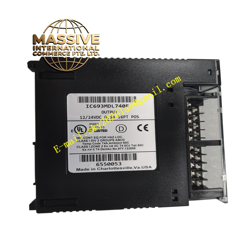
GE IC693MDL740
Technical Specifications:
- Output Type: Positive Logic (Source), 16 discrete output points.
- Grouping: Two independent groups of 8 outputs, each with a dedicated common terminal.
- Operating Voltage: 12 to 24 VDC (Tolerance: +20%, -15%).
- Output Current: 0.5 Amps maximum per point; 2 Amps maximum per common group.
- Response Time: Maximum 2 ms for both ON and OFF states.
- Surge Current: Rated at 4.78 Amps for a duration of 10 ms.
- Voltage Drop: Maximum 1 VDC across the output.
- Leakage Current: 1 mA maximum when in the OFF state.
Functional Features:
- Visual Diagnostics: Front-panel LED indicators provide real-time status for each individual output channel and overall module operation.
- External Protection: Does not include internal fuses; requires external fusing to protect against overcurrent conditions.
- Load Versatility: Capable of driving contactors, relays, indicator lights, buzzers, horns, and solenoids.
- Backplane Power: Draws 110 mA from the 5 VDC backplane bus when all outputs are energized.
Application Scenarios:
- Automation control cabinets for motor starters and contactors.
- Triggering alarm systems, buzzers, and indicator lamps.
- Activating solenoid valves in pneumatic and hydraulic systems.
- General-purpose DC switching in manufacturing and process plants.
Material Composition & Structural Characteristics:
- Enclosure: Ruggedized industrial plastic housing designed for DIN rail or Series 90-30 baseplate mounting.
- Terminals: High-reliability screw terminals for secure field wiring.
- Circuitry: Solid-state transistor outputs with robust thermal management components.
- Dimensions: Compact form factor (approx. 140 x 140 x 30 mm) optimized for high-density panel layouts.
Working Principle: When the PLC logic dictates an ON state, the internal solid-state switch closes the circuit between the positive power bus and the specific output terminal. Current flows from the module, through the external load, and returns to the negative power supply. The module continuously monitors the circuit to ensure safe operation within its rated parameters.
Installation Requirements:
- Baseplate: Installs in any available slot on a 5-slot or 10-slot Series 90-30 baseplate.
- Wiring: Connect the positive side of the external 12-24 VDC power supply to the module’s common terminals. Connect the load between the output terminal and the negative power supply.
- Protection: Install appropriately rated external fuses in series with the load to prevent module damage.
Usage Precautions:
- Current Limits: Ensure the total current drawn by the 8 outputs in a single group does not exceed 2 Amps.
- Inductive Loads: Use flyback diodes or snubber circuits across inductive loads to suppress voltage spikes.
- Heat Dissipation: Maintain adequate ventilation around the module when operating at maximum continuous load.