Description
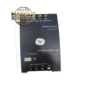
GE IC695PSD040-F
- Technical Specifications:
- Slots: 4 I/O module slots
- Output Voltage: 24VDC (primary) + 5VDC (logic, secondary)
- Output Current: 4A @ 24VDC (96W total)
- Input Voltage: 120VAC or 240VAC (selectable)
- Input Frequency: 47-63Hz
- Voltage Regulation: ±1% over full load
- Ripple and Noise: <100mV p-p
- Isolation: 1500V RMS AC to DC
- Protection: Overcurrent, overvoltage, short circuit, thermal shutdown
- Power Consumption: ~1.5W (self) + load power
- Operating Temperature: 0°C to 60°C
- Dimensions: Compact 4-slot form factor (approx. 150mm x 100mm x 80mm)
- Weight: ~0.8 kg
- Functional Features:
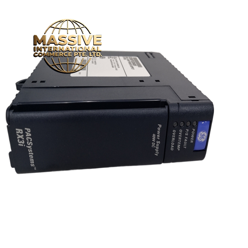
- 4-Slot Chassis + PSU: Combined unit — no separate rack needed
- 4A Current Capacity: Powers up to 4 standard I/O modules easily
- Dual Output: 24VDC for I/O + 5VDC for CPU/logic
- Power Good LED: Indicates when output is within specification
- Fault LED: Indicates overcurrent, overvoltage, or overtemperature
- Universal AC Input: 120/240VAC without hardware change
- Compact Design: Saves panel space compared to separate chassis + PSU
- Application Scenarios:
- Small standalone machines (4 I/O points or less)
- Retrofit projects replacing relays and timers
- Packaging machine sub-systems
- Conveyor control panels
- Educational and training systems
- Remote I/O stations
- Performance Parameters:
- Output Ripple: <100mV p-p at full load
- Efficiency: ~75% at full load
- Transient Response: <10ms from 0 to 4A
- Inrush Current: <20A peak
- MTBF: >100,000 hours
- Bus Speed: 10Mbps VersaMax backplane
- Material Composition:
- Housing: UL94 V-0 polycarbonate/ABS
- PCB: 4-layer FR-4 with conformal coating
- Transformer: Toroidal iron core, encapsulated
- Capacitors: 105°C rated electrolytic, solid polymer for output
- Connectors: Gold-plated backplane edge, AC input terminal block
- Cooling: Passive heat sink fins
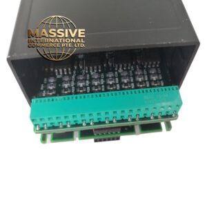
- Structural Features:
- 4 module slots with keyed guides
- Front-panel LEDs: Power (green), Fault (red), Power Good (green)
- Rear-panel AC input terminal block (L, N, G)
- 24VDC output via backplane only
- DIN-rail mountable with included brackets
- Grounding lug for chassis earth
- Working Principle:
- AC mains enters the terminal block and is rectified by a bridge rectifier. The DC is filtered and fed into a high-frequency switching regulator (typically 80-100kHz). The regulator produces a stable 24VDC output for the I/O backplane and a 5VDC output for logic. An opto-isolated feedback loop monitors the 24V output and adjusts the PWM duty cycle to maintain regulation. The power good circuit compares the output voltage to a reference and enables the backplane drive only when voltage is within 22-28VDC. The 4 slots share the 4A current budget — the module limits total current to protect itself.
- Installation Requirements:
- Mount on DIN-rail or panel
- Connect 120/240VAC to the rear terminal block (verify voltage setting)
- Ground the chassis to building earth
- Install I/O modules in any of the 4 slots
- Do not exceed 4A total bus current — calculate module consumption (typical digital module = 100-300mA, analog = 200-500mA)
- Ensure adequate ventilation — do not enclose in a sealed box
- Usage Precautions:
- Verify AC input voltage (120V vs 240V) before powering up — wrong setting destroys the module
- Total current must not exceed 4A — use external 24VDC supply if more current is needed
- Do not block the heat sink fins — overheating causes thermal shutdown
- Check Power Good LED before inserting CPU or critical modules
- Do not hot-swap I/O modules — power down first
- For 4 slots fully loaded with high-current modules, verify total consumption is under 4A (typical max: 4 x 500mA = 2A, well within limit)