Description
GE IC698ACC701
- Technical Specifications:
- Channels: 4 independent high-speed counter channels
- Input Type: Differential (RS-422) or Single-ended (TTL 5V) — configurable per channel
- Maximum Frequency: 5 MHz (differential), 1 MHz (single-ended)
- Counter Resolution: 32-bit signed counter (−2,147,483,648 to +2,147,483,647)
- Input Voltage: Differential: 5V peak-to-peak; Single-ended: 5V TTL
- Input Impedance: 100Ω (differential), 10kΩ (single-ended)
- Isolation: 500V RMS optical per channel
- Backplane Interface: IC698 backplane (90-70 compatible)
- Power Consumption: ~2W
- Operating Temperature: 0°C to 60°C
- Functional Features:
- 4 independent counters with quadrature (A/B/Z) decoding
- Supports up/down counting, modulo counting, latch, and capture
- Hardware-based counting — no CPU scan dependency
- Index (Z) pulse support for home position detection
- Comparator function for position-based output triggering
- Configurable via 90-70 PLC programming software
- LED indicators per channel
- Application Scenarios:
- CNC machine axis position feedback
- Robot joint position monitoring
- Web tension control (roll diameter measurement)
- Conveyor speed measurement via encoder
- Elevator/hoist position tracking
- Wind turbine pitch control
- Performance Parameters:
- Counting Accuracy: ±1 count at maximum frequency
- Response Time: <100ns per count
- Noise Immunity: >1000V common-mode rejection (differential mode)
- Bus Speed: 90-70 backplane, 40Mbps
- MTBF: >200,000 hours
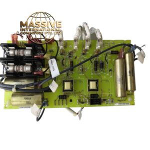
- Material Composition:
- Housing: UL94 V-0 polycarbonate/ABS
- PCB: 6-layer FR-4, conformal coated
- Connectors: High-density D-sub or screw terminals (per channel)
- Isolation: High-speed opto-isolators (LED + phototransistor)
- Input Receivers: RS-422 line receivers (AM26C32 or equivalent)
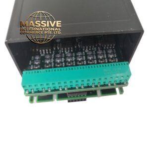
- Structural Features:
- Standard IC698 module form factor
- 4 LED status indicators (one per channel)
- Screw terminals or D-sub for encoder connections
- DIN-rail or chassis mount
- Working Principle:
- Encoder A/B signals are fed into high-speed RS-422 receivers. An internal FPGA/ASIC decodes the quadrature signals, determining direction and accumulating counts in 32-bit registers. The Z (index) pulse resets or latches the counter. The CPU reads counter values via the 90-70 backplane bus. Hardware counting ensures zero missed counts even at 5 MHz.
- Installation Requirements:
- Mount in IC698 chassis (90-70 compatible)
- Use shielded twisted-pair cable for encoder connections
- Ground shield at one end only (chassis ground)
- Set input type (differential/single-ended) via DIP switches or software
- Keep encoder cables away from power cables (>30cm separation)
- Usage Precautions:
- Do not exceed 5V on single-ended inputs — will damage receivers
- Use differential mode for noisy environments (always preferred)
- Do not exceed 5 MHz frequency — use appropriate prescaler if needed
- Verify encoder signal voltage matches module specification
- Add external pull-up resistors only if required by encoder type
- Do not hot-swap — power down before installation