Description
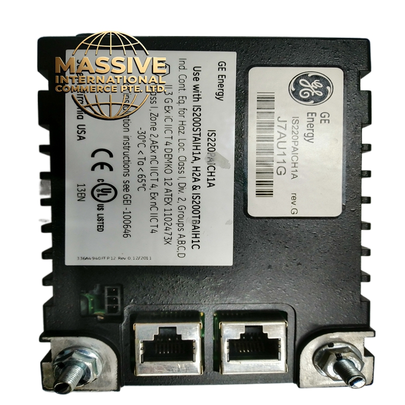
GE IS220PAICH1B
Technical Specifications
| Parameter | Specification |
|---|---|
| Function | Analog Input/Output Interface |
| System Compatibility | Mark VIe I/O Pack |
| Input Channels | Multiple analog inputs (4-20mA, 0-10V, thermocouple, RTD) |
| Output Channels | Multiple analog outputs (4-20mA, 0-10V) |
| A/D Resolution | 16-bit or higher |
| D/A Resolution | 16-bit or higher |
| Isolation | Channel-to-channel and channel-to-ground isolation |
| Update Rate | < 10ms for all channels |
| Accuracy | ±0.1% of full scale typical |
| Field Power | 24V DC loop power supply |
| Operating Temperature | -30°C to 65°C (-22°F to 149°F) |
| Storage Temperature | -40°C to 85°C (-40°F to 185°F) |
| Humidity | 5% to 95% non-condensing |
| Enclosure | IP20, DIN rail mountable |
Functional Features
-
Multi-Range Inputs: Software-configurable input ranges for various sensor types
-
Loop Power Supply: Provides 24V DC excitation for 2-wire transmitters
-
Linearization: Built-in thermocouple and RTD linearization tables
-
Cold Junction Compensation: Automatic compensation for thermocouple inputs
-
Broken Wire Detection: Detects open circuit conditions on 4-20mA inputs
-
Output Hold: Maintains last output value on communication failure
-
HART Protocol Support: Enables communication with smart field devices
Structural Characteristics
-
Compact DIN rail mountable enclosure
-
Removable terminal blocks for easy wiring
-
LED status indicators for each channel
-
Ruggedized design for harsh industrial environments
-
Conformal coated PCB for moisture and chemical resistance
Working Principle The I/O pack receives analog signals from field sensors and transmitters. Each input channel includes signal conditioning, isolation, and analog-to-digital conversion. The digital values are transmitted to the control processor via the IONet or Ethernet network. For outputs, the pack receives digital values from the processor, converts them to analog signals via digital-to-analog converters, and drives field actuators such as control valves or variable speed drives.
Installation Requirements
-
Mount on DIN rail in control cabinet
-
Connect field wiring to removable terminal blocks
-
Configure input types and ranges using system software
-
Ensure proper shield grounding for analog signals
-
Maintain separation between analog signal cables and power cables
Application Scenarios
-
Process variable monitoring (temperature, pressure, level, flow)
-
Control valve position feedback and command
-
Variable speed drive analog references
-
Environmental monitoring systems
-
Auxiliary system control in power plants
Usage Precautions
-
Verify correct input range configuration before applying signals
-
Ensure proper grounding to avoid ground loop errors
-
Do not exceed rated input voltages
-
Use shielded cables for low-level signals
-
Regular calibration verification recommended