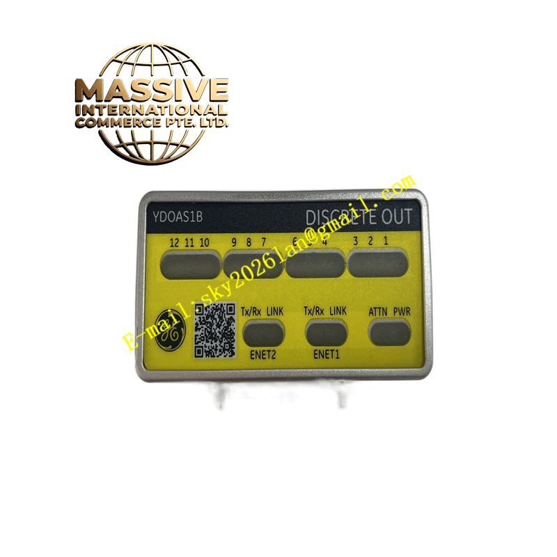
Description
GE IS420YDOAS1B Technical Specifications:
- Output Type: Discrete (relay or solid-state, depending on variant).
- Channel Count: Multiple independent output channels.
- Voltage Rating: Compatible with standard industrial control voltages (24VDC, 120VAC, 240VAC).
- Current Rating: Rated for continuous industrial loads.
- Isolation: Channel-to-channel and channel-to-bus galvanic isolation.
Functional Features:
- High-Capacity Switching: Designed to handle inrush currents of motors and solenoids.
- Status Indication: Visual LED indicators for each output channel.
- Diagnostic Feedback: Open-circuit and short-circuit detection (on advanced variants).
- Safety Compliance: Designed to meet SIL (Safety Integrity Level) requirements.
Application Scenarios:
- Motor starter and contactor coil control.
- Solenoid valve actuation in hydraulic and pneumatic systems.
- Alarm horn and beacon control.
- Safety system interlocks and permissives.
Performance Parameters:
- Response Time: Fast actuation and release times.
- Mechanical Life: High-cycle rated for long service life.
- Electrical Life: Optimized for inductive load switching.
Material Composition & Structural Characteristics:
- Contacts: Silver-alloy contacts for high wear resistance.
- PCB: Heavy copper traces for high-current paths.
- Enclosure: Protective housing with environmental sealing.
- Terminals: Screw or plug-in terminals for secure connections.
Working Principle: The module receives digital output commands from the controller over the I/O bus. The onboard driver circuitry energizes the relay coils or solid-state switches, closing or opening the output contacts. This switches the external load circuit. Diagnostic circuits continuously monitor the output state and load current to detect faults.
Installation Requirements:
- Load Rating: Verify that the connected load does not exceed the output rating.
- Inductive Loads: Use snubber circuits or flyback diodes for inductive loads.
- Wiring: Use appropriate wire gauge for the load current.
- Testing: Manually test each output during commissioning.
Usage Precautions:
- Contact Life: Be aware of mechanical and electrical life limits.
- Inrush Current: Account for inrush current when switching capacitive or lamp loads.
- Safety: Always de-energize loads before servicing the module.
- ESD Protection: Use proper ESD precautions when handling.